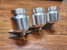
Rick's Active Power GT40 Build

1000001313.jpg
1000001312.jpg

Machined a bracket amd fittings for a nice billet set of brake and clitch reservoirs.
 

Attachments

  • 1000001313.jpg
    1000001313.jpg
    597.6 KB · Views: 21
Got the sway bars mounted. Speedway engineering parts. Arms come as flat bars. I cut them at the bend, leaving 1/16 of material on the inside. Then they can be bent by hand to the right angle and just weld up the V.

20240205_205243.jpg
 
Last edited:

Mark Turner

Supporter
My big feet wouldnt go around the steering shaft, so i rotated the rack so that the input shaft is vertical. Installed a bevel gear unit to make a right angle away from the feet.
View attachment 135067

The coyote is drive by wire. I cut the gas pedal and made a linkage so that it acts as a sensor. Made a pair of aluminum plates to allow gas pedal adjustment in x and y so I can dial that pedal in for the right feel.

View attachment 135068
Hello Rick can I ask your source and maybe a part number for the bevel gear?
 
I think I worked out a good way to route the heater core plumbing. The coyote engine circulates the heater core coolant even before the thermostat opens, so I routed tubing through the center section for both supply and return. This tubing is 5/8" 304 stainless with a fiberglass and silicone insulating sleeve. 5/8" silicone tubing connects the stainless lines at the front with the heater core through the firewall. Rubber grommets seal the tubing to the firewall and a simple solenoid type heater valve in line to be controlled by the AC/Heat electronics later on. The whole setup stays to the rear to avoid interfering with the nostrils.

20240213_203240.jpg


20240213_203256.jpg
 
I got the evaporator / heater core mounted and plumbed. Used some 3/4" square tubing to mount the side brackets and allow the unit to slide forward and back until it's nailed down. I used some aluminum lines from vintage air to run down the passenger side, just inside the fuel tank. When the side panels are attached, these lines will be out of sight. Bulkhead fittings go through the firewall and change to rubber hose.

20240213_202634.jpg

These will get clamped down when the evaporator is secured, but you can see the routing. Used a 135 degree fitting for the -6 line and a 90 degree fitting for the -10. I had to mount the unit as far to the passenger side as possible to avoid my feet hitting it above the gas pedal. It barely clears.

20240213_202650.jpg


Here are the lines in front of the firewall.

20240213_203311.jpg


Here are the lines going to the condenser. I won't connect the -6 lines until I'm ready to fill it to save the drier media.
.
20240213_203304.jpg
 
So here's a look at the whole front section currently. I had to reroute the coolant lines a bit to make room for my spun aluminum air tank. This tank will hold pressure for the suspension lift system. Each coilover has an air piston attached that will be able to lift the car 3" or so to clear speed bumps and steep drives.

20240213_213940.jpg


Of course all of this still has to clear the nostrils...

20240213_214051.jpg


Here is a coilover with piston attached.

20230606_171338.jpg
 
I did a lot of searching for duct parts to use with the AC system but couldn't find what I wanted. It looks like the default install from vintage air has the output air blowing to all vents and a cable operated baffle for the defroster. I wanted to control the blower output more like a modern car with dash output, floor output, and defroster selectable electronically. I'll make the electronic controller later on, but first I need the hardware to be able to control the air output. Not finding anything else suitable, I bought some 12v, 75mm baffles made in china. I took the motors off of them and designed a new baffle assembly the correct size to fit the 2.5" flex tubing and vents in the GT. I printed the design on the 3d printer and voila', new baffles.

20240213_202930.jpg


20240213_202906.jpg


I'll make 4 of these and connect them to the blower plenum.
 

Randy V

Moderator-Admin
Staff member
Admin
Lifetime Supporter
Looking really good Rick! I’m looking forward to checking it out in person in a couple months when I get home…
Curious about this bevel-gear system. Because one bevel driving another will reverse the direction of the input - there must be an intermediate gear.
 
Looking really good Rick! I’m looking forward to checking it out in person in a couple months when I get home…
Curious about this bevel-gear system. Because one bevel driving another will reverse the direction of the input - there must be an intermediate gear.
Randy,

If the bevel gears are configured like the diagram below, they do not reverse direction. It's a 1:1 ratio input to output.

1707935046919.png
 

Randy V

Moderator-Admin
Staff member
Admin
Lifetime Supporter
Of course you’re correct Rick,,, I must‘ve applied the physics of 2 spur gears by mistake…. Thanks for setting me straight!
 
Back
Top