Rick's RCR GT40

Rick Merz

Lifetime Supporter
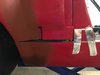
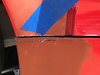
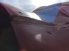
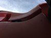
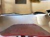
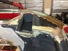
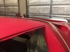
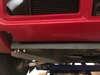
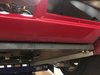
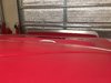
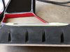
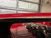
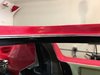
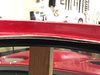
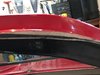
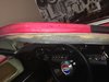
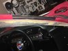
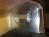
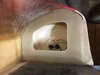
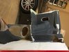
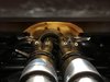
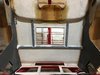
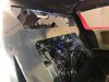
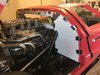
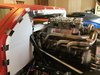
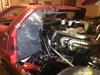
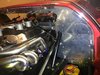
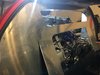
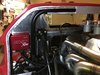
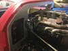
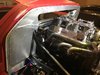
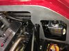
Double bulkhead construction, I first modified and relocated my roll bar to the rear of the car by about 2" (post 93). I requested (from Fran and was delivered rather promptly) a new stock bulkhead (minus all holes including the rear window cut out) that I could modify to accommodate a Tornado glass rear window that will be mounted in a slightly lower position than the RCR window. I made a poster board pattern of the inner "A" pillar/roof profile that I transferred to the bulkhead and cut out, after a little grinding it fit like a glove. I then marked where the roll bar would be and laid out the rear window opening and cut it out. I then installed the inner bulkhead and started to design the rear bulk head.

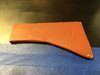
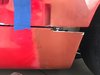
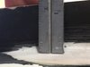
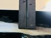
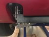
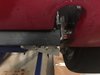
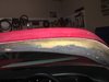
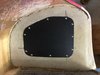
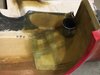
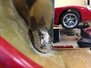
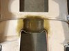
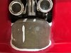
I wanted the bulkhead to hide the ECU's and the radiator header tank since I prefer a cleaner look in the engine compartment and I will vent A/C to the ECU's to keep them cool. I used 1/8" poster board (heavy weight paper/foam/heavy weight paper) to mock up the bulkhead and roll bar cover. After getting the exact profile for the bulkhead, roll bar cover and inner panels that connect the two bulkheads together I printed out 1" x 1" graph paper big enough the trace all of the poster board cutouts. I then had to measure hundreds of points to 1/64" accuracy and input all of the points into AutoCAD to make a drawing that was used to program the laser cutter. The laser cutter's accuracy is so good that it can cut out even the small pilot holes for the 8-32 screws and 1/8" rivets that will be used to assemble the two bulkheads and inner panels. Next I had to bend a 5/8"x 5/8"x 1/16" aluminum angle that will be drilled on one toe for rivets that will attach it to the "A" pillar and drilled on the other toe to mount nut-inserts so that the bulkhead can be mounted to the "A" pillar/roof. I used a metal shrinker and stretcher from Eastwood to shape the angle to follow the "A” pillar/roof profile. This was my first time using a metal shrinker and stretcher and the final product turned out very nice with no gaps when installed. After forming and mounting the angle I attached all of the panels with 8-32 screws to the nutserts in the angle, I then removed the panels and sanded them to get them ready for paint which will take place after the car is painted.
 

Attachments

  • IMG_3870 1020.jpg
    IMG_3870 1020.jpg
    201.4 KB · Views: 893
  • IMG_3742 1020.jpg
    IMG_3742 1020.jpg
    255.6 KB · Views: 878
  • IMG_3744 1020.jpg
    IMG_3744 1020.jpg
    265.4 KB · Views: 852
  • IMG_3867 1020.jpg
    IMG_3867 1020.jpg
    295.6 KB · Views: 872
  • IMG_3872 1020.jpg
    IMG_3872 1020.jpg
    285.8 KB · Views: 858
  • IMG_3940.JPG
    IMG_3940.JPG
    319.3 KB · Views: 866
  • IMG_4087 1020.jpg
    IMG_4087 1020.jpg
    284.8 KB · Views: 835
  • IMG_3928 1020.jpg
    IMG_3928 1020.jpg
    208.3 KB · Views: 840
  • IMG_3935 1020.jpg
    IMG_3935 1020.jpg
    270 KB · Views: 714
  • IMG_4512 1020.jpg
    IMG_4512 1020.jpg
    258.8 KB · Views: 887

Rick Merz

Lifetime Supporter
Brian, Thanks, like you I was a millwright early in my career and my father was a toolmaker, I have always liked to create things with my hands which usally prompted my father to say "Who made this mess? Get it cleaned up now!". :)

Lee, Thanks, the aluminum angle is riveted to the rear edge of the spider and the bulkhead is secured with screws that screw into nut-inserts that are set into the other toe of the angle. I did it this way so that the entire bulkhead system and the access panels can be removed if needed. I will have to completely remove it after the car is painted so that I can paint the rear bulkhead.
 
Last edited:

Rick Merz

Lifetime Supporter
Now that most of the mechanical work has been completed it's time to start working on the body.

I am going to start with the rear deck since there is a lot of work to be done to make it right. I ordered the +4 flairs and paid an additional $500 to have them put on, well I think that it's going to take many hours just to fix the rear clip and rocker flair extensions.

The issues are:

1. The flair on the right side sticks out from the flair on the rocker by 9/16" and I had to cut the flair from the rocker and remove 5/16" just to get the clip to close (the flair angled up that much). There is a large void in the flair on the rocker as well.

2. The flair on the left side sticks out from the flair on the rocker by 9/16" and I had to cut the flair out from the rocker and remove 1/4" just to get the rocker to sit flush with the top of the mounting surface (the flair angled DOWN that much).

3. When the flairs were bonded the the clip there was a ridge that was about 1/2" tall and 3/4" wide all the way around which I had to grind flush and add 4 layers of fiberglass to strengthen the joint. Grinding fiberglass in 95° heat is a bitch! What could I do it looks terrible, how could I open the clip to show off my engine with that huge ridge?

To be continued...
 

Attachments

  • IMG_0438 1020.jpg
    IMG_0438 1020.jpg
    133.1 KB · Views: 833
  • IMG_1735 1020.jpg
    IMG_1735 1020.jpg
    187 KB · Views: 789
  • IMG_1736 1020.jpg
    IMG_1736 1020.jpg
    151.5 KB · Views: 793
  • IMG_1737 1020.jpg
    IMG_1737 1020.jpg
    115 KB · Views: 775
  • IMG_0434 1020.jpg
    IMG_0434 1020.jpg
    260.1 KB · Views: 785
  • IMG_1738 1020.jpg
    IMG_1738 1020.jpg
    162.5 KB · Views: 764
  • IMG_1551 1020.jpg
    IMG_1551 1020.jpg
    247.7 KB · Views: 773
  • IMG_1554 1020.jpg
    IMG_1554 1020.jpg
    260.2 KB · Views: 734
  • IMG_1567 1020.jpg
    IMG_1567 1020.jpg
    243.8 KB · Views: 732
  • IMG_1652 1020.jpg
    IMG_1652 1020.jpg
    217.5 KB · Views: 780

Rick Merz

Lifetime Supporter
Rear deck issues continued...

4. When the inner panel was bonded to the rear deck outer skin the right side was inset 1-3/16" to the edge and the left side was inset 11/16". Because of this the left side would rub the cut edge at the rear of the spider (after it was cut to the correct length) and I did not want to cut it at an angle or cut it too short. The root cause is that it was not assembled correctly so I have to cut the inner and outer skins apart
(black line in picture) and move the surface in an additional 1/2" so that the right and left sides match. After checking for correct fit I fiber glassed the parts together and filled to as needed, the clip closes properly now. I should have checked the rear clip for defects and returned it to the manufacturer for replacement.

5. So after I take the car out for it's first short drive I park it in the garage (not on the lift) and I notice that rear clip is setting low on the right side so I get out my 8' level and use it for a reference to measure with and I discover that the right rear corner is 5/16" lower than the left rear corner (see pics 4297 & 4298 rear of tray is level). Everything else about the clip fits perfectly (see pic 4292 top edge of clip is flush to the roof) I spent about 20 hours going back and forth until it fit right (or so I thought). The car was on the lift while I was doing the fitting so I never noticed the "tilt". When I made the clip level at the lower rear edge (see pics 4290 & 4291) the left front top corner lifted up 1/2" above the roof (see pic 4281). So here is where I am at today frustrated beyond belief, I do not know how much I have to cut apart (the inner / outer shell) to relax it so that is will sit flush at the roof line and be level to the ground. I will not accept the twist and right now I am not sure about my next move so I welcome all input to correct this problem. No one should have to put this much work into a body to make it look good! This is not an alignment issue this is a workmanship issue that could have been avoided. I have only talked about the rear clip / rocker flairs so far... There are issues with the doors, spider and front clip that I have not posted about yet... It is one thing if we choose to modify something for a different purpose or look it is a different issue when poor workmanship is sold to us. Please understand that I love everything about my RCR GT 40 EXCEPT the body.
 

Attachments

  • IMG_2517 1020.jpg
    IMG_2517 1020.jpg
    159.9 KB · Views: 568
  • IMG_2522 1020.jpg
    IMG_2522 1020.jpg
    211.1 KB · Views: 691
  • IMG_2659 1020 Marked up .jpg
    IMG_2659 1020 Marked up .jpg
    281.9 KB · Views: 735
  • IMG_4281 1020.jpg
    IMG_4281 1020.jpg
    265.4 KB · Views: 703
  • IMG_4290 1020.jpg
    IMG_4290 1020.jpg
    199.2 KB · Views: 710
  • IMG_4291 1020.jpg
    IMG_4291 1020.jpg
    202.4 KB · Views: 729
  • IMG_4292 1020.jpg
    IMG_4292 1020.jpg
    260.3 KB · Views: 706
  • IMG_4297 1020.jpg
    IMG_4297 1020.jpg
    190.6 KB · Views: 698
  • IMG_4298 1020.jpg
    IMG_4298 1020.jpg
    192.9 KB · Views: 720

Bill Kearley

Supporter
I feel for you. CAV has some serious issues as well. I haven't done a final body fit yet but the fire wall is 5/8 of an inch back on the drivers side compared to the passenger side, the spider is a mess and requires a major twist on the left B pillar to get straight. I can't imagine what I will be facing at the final fitment. and mine has a final paint job from Gulf and CAV that I paid a lot extra for. If the manufactures want to frustrate customers to this point they should pack it in. I think complaints should go public like this to make them aware and may be improve the product.
 

Rick Merz

Lifetime Supporter
I agree, had I known these issues I would have bought the RCR kit (I am very pleased with Frans kit except for the body that was not made by him) less body and I would have purchased the body from Bill Hough owner of William J Hough Composites. He is a great guy that makes a quality body.

Link http://houghcomposites.wix.com/site
 
Last edited:

Rick Merz

Lifetime Supporter
Door issue...

The doors as received from RCR were cut about 1/8" too short at the bottom. No good if you want a 1/8" to 3/16" gaps (see pics 1741 & 1742). Ok if you want 1/4" to 5/16" gaps which are too wide for me. I had to grind the bottom of both doors to a wedge profile which will allow me to build the edge back with fiberglass (see pic 2182). after grinding very carefully as to not shorten the door skin further I made a backing strip out of multiple layers of aluminum duct tape and marked it with a Sharpie so that I would have a rough cut line to guide me when I cut off the excess fiberglass (see pic 2181 & 2187). Finished product before gaping (pics 2212 & 2258).

This repair was very easy to avoid if the doors were trimmed properly by RCR's vendor but they weren't which required more of my time working with fiberglass (which I do not like to do).

I will post door modifications and repairs, that I made because I wanted the modifications and one major mistake that I made which required more work than the above repair, in upcoming posts.
 

Attachments

  • IMG_1741 1020.jpg
    IMG_1741 1020.jpg
    241.6 KB · Views: 594
  • IMG_1742 1020.jpg
    IMG_1742 1020.jpg
    293.4 KB · Views: 561
  • IMG_2182 1020.jpg
    IMG_2182 1020.jpg
    154.7 KB · Views: 670
  • IMG_2181 1020.jpg
    IMG_2181 1020.jpg
    208.1 KB · Views: 694
  • IMG_2187 1020.jpg
    IMG_2187 1020.jpg
    190.9 KB · Views: 688
  • IMG_2212 1020.jpg
    IMG_2212 1020.jpg
    253 KB · Views: 650
  • IMG_2258 1020.jpg
    IMG_2258 1020.jpg
    243.5 KB · Views: 708

Rick Merz

Lifetime Supporter
Spider issue...

The ledge that is formed when the outer spider roof skin is bonded to the inner spider skin for the door seal to clip onto varies from 1/8" (good. right side of pic 2326) to 1/2" (very bad, pic 2329). This is caused from chopper gun layup when the operator stays in one place too long. If the thickness would have been checked and sanded to the correct thickness before bonding the two surfaces together as well as clamping better to control the thickness of the bonding agent then a better final product would have been sent to the customer. If RCR would have done some incoming quality inspections as well as having thickness specifications on the fiberglass layup then defective parts could be sent back for replacement since they would not have been produced to the print. After sending back a couple of body parts the company supplying these parts would have gotten their act together and make quality parts since they would quickly learn that if they don't make quality parts (as per the print and specifications) they don't get paid.

I had to sand off (remove) the lip of the inner liner and sand the lip of the outer shell to 1/16" thick on 80% of BOTH door openings. This is very tedious work to say the least (dislike fiberglass so much now) but I'm just getting started. After sanding the lip off the inner liner the physical bond between the two panels was removed so I fiber-glassed the lip back onto the inner liner and onto the outer liner. I layed it up a little thick (1/32") so that I could sand it instead of using filler to smooth the surface. Again this was work that I should not have had to do, I can only imagine what all of this work would have cost if I hired a body shop to prep the body.

I do not want to sound like I am bitching, I am giving honest feed back on my experiences with my build, like I have said before I am very pleased with Frans kit EXCEPT for the body that was not made by RCR.
 

Attachments

  • IMG_2325 1020.jpg
    IMG_2325 1020.jpg
    296.9 KB · Views: 645
  • IMG_2326 1020.jpg
    IMG_2326 1020.jpg
    146.1 KB · Views: 504
  • IMG_2327 1020.jpg
    IMG_2327 1020.jpg
    162.2 KB · Views: 656
  • IMG_2329 1020.jpg
    IMG_2329 1020.jpg
    193.6 KB · Views: 644
  • IMG_4588 1020.jpg
    IMG_4588 1020.jpg
    182.6 KB · Views: 686
  • IMG_4589 1020.jpg
    IMG_4589 1020.jpg
    209.1 KB · Views: 651
  • IMG_4590 1020.jpg
    IMG_4590 1020.jpg
    173.4 KB · Views: 651

Rick Merz

Lifetime Supporter
I tried to call Fran several times this past summer but he was either gone or not available (major project for RCR at the time) but I think that he is aware of some of my problems and if he checks my posts then he will be up to speed with what I have had to go through (it is part of the reason that I made them). Hopefully he will have a "come to Jesus" (as they say in the South) talk with his supplier and can get better quality bodies in the future.

I am thinking that to make the rear deck level I will have to cut the wide body flares loose (not looking forward to that at all) so that the deck can flex about 5/32" (half of the 5/16" that it is twisted) so that the front and rear of the clip will be level to each other. I am putting this off hoping others would chime in on post # 106. No matter how good any one of us may be, all of us are much smarter and more skilled than any one of us, this is why I read almost every build thread on this site, there are a lot of very talented and knowledgeable people posting on this site.
 
Last edited:

Brian Kissel

Staff member
Admin
Lifetime Supporter
I tried to call Fran several times this past summer but he was either gone or not available (major project for RCR at the time) but I think that he is aware of some of my problems and if he checks my posts then he will be up to speed with what I have had to go through (it is part of the reason that I made them). Hopefully he will have a "come to Jesus" (as they say in the South) talk with his supplier and can get better quality bodies in the future.

I am thinking that to make the rear deck level I will have to cut the wide body flares loose (not looking forward to that at all) so that the deck can flex about 5/32" (half of the 5/16" that it is twisted) so that the front and rear of the clip will be level to each other. I am putting this off hoping others would chime in on post # 106. No matter how good any one of us may be, all of us are much smarter and more skilled than any one of us, this is why I read almost every build thread on this site, there are a lot of very talented and knowledgeable people posting on this site.
 

Brian Kissel

Staff member
Admin
Lifetime Supporter
Rick, do you know which supplier made them for RCR? I thought at one time, someone in Canada was making bodies for them.
 

Rick Merz

Lifetime Supporter
Rear Clip Modifications...

Some people will probably shake their head and wonder why I would do some of the mods that I am about to talk about, but I have an idea of what I want and the reasoning that supports my idea. Remember I am not building a replica that will be as accurate as possible (that may be my next build), this build is meant to be beautiful, fast, cold (A/C), and reliable as a modern factory built car (notice that I left out comfortable :) ). I do not care if the engine requires regular maintenance (adjusting solid roller rockers for instance) or if I may have to replace an A/C compressor because I spun it too fast on the track, as long as I don't sweat my butt off and it doesn't break down then my build will be a success for me. My GT40 will be driven on the track (including the drag strip), highway, go to work and even in the rain. I participated in 3 track events in the past that had rain on at least 1 of the days of the event and on all three occurrences I was the only GT40 on the track and I was having a blast. When rain days happen at these events they usally run an open session where all cars can go out but usally the track is pretty empty.

1. Close in the rear tail lights - I made a cardboard mold and taped it into place very carefully so that I could remove the tape and cardboard mold after laying the fiberglass. To remove the cardboard mold I cutout the access hole and reached in and peeled the mold out piece by piece. I then sanded the fiberglass smooth. After the lights were closed in I made a fiberglass cover to close off the access hole. I drilled and installed nut inserts and installed the cover. I did this because I like the cleaner look and it keeps the lights clean.

2. Close in the front of the wheel well - I made a paper mold for this since I would not be able to remove it after the fiberglass was applied. I carefully laid up one layer of fiberglass mat and let it cure so that I could have a better surface to add the additional 2 layers of fiberglass mat. After the fiberglass cured I sanded it smooth. I did this modification because I didn't like the different surfaces showing and I wanted a cleaner looking wheel well with less turbulent air.

3. Remove the curved surface from the inner (flat) wheel well - I cut out the curved surface and closed it with fiberglass making it flush to both sides of the flat surface. This was done because I like the look of a smooth flat surface. I also want to reroute the air that was supposed to go to the rear brakes since I want the air to blow onto the headers to help keep the engine compartment cool. I will get air to the rear brakes by installing snorkels and brake duct hose (to be done in the future).

4. Route air from rear brakes to engine compartment - I cut the fiberglass brake ducts (supplied by Hough Composites) to be flush with the curved surface that I molded into the front of the wheel well. I cut oval holes into the flat surface that I created in the flat wheel wells. I used left over 2" flexible a/c vent tube (2 pieces laid side by side) taped together with plastic duct tape to serve as the mold for the end of the air duct. I also used the same tape on the inside of the tubes to connect them to the flat inner wheel that I cut the holes into. I laid up the fiberglass and removed the flexible a/c tube by pulling it out from the exit hole in the flat panel. After sanding the duct looks pretty good, I can't locate a picture but I will take one and include it with my next post. As I said above this modification was done to supply air to the engine compartment to help keep it cool.

5. Hump for header clearance - The headers that RCR supplied are beautiful and very well built. The only problem is that they replicate the big block MK II system in a MK I car. Because of this the rear deck had to be cut to allow it to close which left me 2 choices, I could either cut the area under the window out like a MK II car or make a hump in the area where the header tube hits the rear deck. I chose to make a hump since I want to limit hot engine air from entering the engine through the throttle bodies. I made a mold out of cardboard and covered it with several layers of aluminum duct tape to smooth the surface and to make it stronger. I then laid up the fiberglass and sanded it smooth. In the end I think that it looks about as good as it can (would have preferred to not have done this modification). Astute eyes will notice that I also cut the two rear exhaust tubes to reroute them so that they would be lower since they also came in contact with the rear deck when it was closed, more about that in a later post.

6. Added Fiberglass tubing to the underside of the deck - I cut and expoied 1" x 1" x 1/8" thick fiberglass tube to the underside of the deck to stiffen it up and to mount the heat shield to it (to be done in the future).
 

Attachments

  • IMG_1990 1020.jpg
    IMG_1990 1020.jpg
    303.8 KB · Views: 646
  • IMG_1996 1020.jpg
    IMG_1996 1020.jpg
    223.9 KB · Views: 637
  • IMG_2016 1020.jpg
    IMG_2016 1020.jpg
    239.4 KB · Views: 639
  • IMG_2115 1020.jpg
    IMG_2115 1020.jpg
    202.1 KB · Views: 501
  • IMG_2667 1020.jpg
    IMG_2667 1020.jpg
    214.4 KB · Views: 646
  • IMG_2409.JPG
    IMG_2409.JPG
    308 KB · Views: 644
  • IMG_2119 1020.jpg
    IMG_2119 1020.jpg
    225.8 KB · Views: 641
  • IMG_2135 1020.jpg
    IMG_2135 1020.jpg
    234.1 KB · Views: 670
  • IMG_2144 1020.jpg
    IMG_2144 1020.jpg
    183.7 KB · Views: 678
  • IMG_2677 1020.jpg
    IMG_2677 1020.jpg
    256.2 KB · Views: 552

Brian Kissel

Staff member
Admin
Lifetime Supporter
Click on the 40. From their website, it looks like they make the 917, the SLC, and the Nemesis. The 40, on their page looks like Rons car.
 

Rick Merz

Lifetime Supporter
Brian, That's what I get for reading and assuming. :) I didn't click on the picture.

Sean, I am pretty sure that Fran purchased a body from Hough Composites but I do not recall the conversation that I had with Bill so I will post an accurate answer after I talk to bill again.
 

Chris Kouba

Supporter
Holy crap Rick. I cringe for you... At least when I screwed up my body, I had only myself to blame. I would be way less even-tempered about the issue than you appear to be. Tip of the hat to you!

It was interesting to read your intended objective for this build as it is fairly similar to mine- I wanted a driver, modest power, reliable, and moderately comfortable. I do intend to do some touring out of it, but we'll see how that goes. I remember seeing your GTD when I first joined the forum and was bummed to not be in a position to pick it up when it was available. Looking forward to seeing what you do with this one, it should look great by the time you're done!
 
Back
Top