Roaring Forties 105

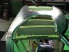
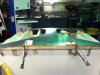
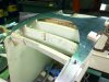
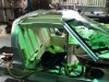
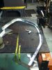
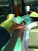
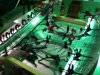
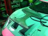
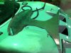
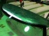
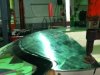
Ok well the roof that was interesting I had 2 goes at this and ran out of talent.
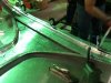
My thought prosses was that I roll it as one section , I then cut out the door apartures and use them in the top of the doors.

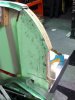
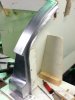
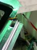
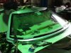
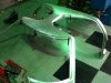
The roof is a constant radius front to rear left to right with the crown at about the 250-300mm back from the top of the screen.

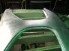
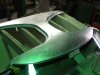
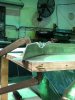
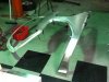
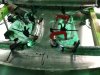
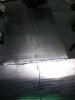
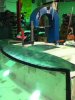
It requires a lot of shrinking on the sides above the side windows , the second one looked fairly close but in the end I opted to make the roof in sections as it is a T section anyway it is so much easier to handle.
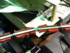
At the end of the day it was a lot of metal and it wasnt happy.

I will continue on with the roof and post when I have something more finished.

jim
 

Attachments

  • IMG_0048.JPG
    IMG_0048.JPG
    243.9 KB · Views: 450
  • IMG_0055.JPG
    IMG_0055.JPG
    281 KB · Views: 458
  • IMG_0053.JPG
    IMG_0053.JPG
    197 KB · Views: 425
  • IMG_0054.JPG
    IMG_0054.JPG
    315.4 KB · Views: 458
Last edited:

HILLY

Supporter
Love your work Jim.
I would be happy with only half the talent that you have on display here.
Looking forward to the progress updates.
 
Hi Jim, I have watched a guy make complete wings of unbelievable shapes for old Astons and Porsches. It's an art and they do it without thinking about it too much.
Practice makes perfect but I think your doing a great job, especially for an Aussie !
Interesting to watch the progress.
Cheers
 
Hey Jim.
I don't get on here much. Glad you have RF105 registered!!!
Your patience and commitment to "getting it right" is commendable.
Keep at it....

Tim.
 
Thanks Guys.


Well I had a week to think about the roof and I figured out how to go about it this was the results today.
Wheeled out the skin,made the front rear flanges and one door seal flange.

Very happy it is one piece.

Jim
 

Attachments

  • roof 1.JPG
    roof 1.JPG
    245.7 KB · Views: 522
  • roof 6.JPG
    roof 6.JPG
    264.2 KB · Views: 406
  • roof 9.JPG
    roof 9.JPG
    260 KB · Views: 438
  • roof 14.JPG
    roof 14.JPG
    307.7 KB · Views: 507
Last edited:
Thanks Mark

I have got more done over the week.
I have also had a few emails and a PMs asking if I could give more detail on the making of the roof.
It will be easier if I put it up here rather than do it through email as it will end up double doing.
The ply pattern is half the trick, it is within about 1-3 mm of my car.
You have to have a datum, this I took from 10mm forward of the rear of the pontoon in the eng bay.
I put 2 texter marks across the pontoon running left to right to shoot a laser onto.
All longitudinal measurements are taken from this point, EG rear off roof, top of screen, bottom of screen.
I used plumb bobs a long alloy section set level down the centre line of the car to drop down off.
The top surface of the pontoon was my datum for any measure above or below.
I purchased 4 profiling tools and linked them together.
 

Attachments

  • IMG_0117.JPG
    IMG_0117.JPG
    273.6 KB · Views: 420
Cut the doors out of your roof sheet before you start wheeling
I ran tape on the c/line and every 150mm of to the left on the roof of my car.
I built the rear bulk head on the buck to mount the roof profiles into.
Using the profile tool I ran it along the tape line at the c/line and transferred it onto the plywood.
Using the laser I set its height off the pontoon as it was set on my car when I measured it, this then I use to find the height of the rear and front of the roof profile that I had recorded.
Everything in between is a given as it came of the profile tool.
The 2nd 3rd and 4th profile you cut 2 off and repeat the install as the 1st.
You double check ,triple check your measure, I use a seamstress tape a lot as it follows the profiles to true length and laser to XYZ.
I found screen location was the hardest to finalize, it should have been straight forward but it wasn’t.
You need a screen to do this project.
start wheeling it
Wheel the sheet with the flat lower anvil wheel on the English wheel and get some compound.
using a shrinker across the rear and front edge it will bring it up fast almost there if you know what I mean.
Go to the next radius anvil and gently wheel it up.
Around the front I use a rubber band on the top wheel and it will make the sheet radius but not compound, I run around in an arc so the roof starts to pull down into the top of the screen.
 

Attachments

  • IMG_0105.JPG
    IMG_0105.JPG
    293.1 KB · Views: 394
Last edited:
It goes on the ply buck numerous times while this is going on just to check yourself.
The side legs are completely made on the buck, tacked then removed for final welding, it is 5 sections.
3rd shot is as per earlier,put it in again to show location on buck.
 

Attachments

  • IMG_0102.JPG
    IMG_0102.JPG
    260.6 KB · Views: 372
  • IMG_0103.JPG
    IMG_0103.JPG
    274 KB · Views: 348
  • IMG_0026.JPG
    IMG_0026.JPG
    248.8 KB · Views: 367
Looking good Jim
How far are you going with the 40 body ?
Will you be making the front and rear clips as well ?
You'll have an Alan Mann replica soon :stunned:

Clayton
 
All the door, screen and rear flanges are made separate they go through the shrinker or stretcher to get the final shape, they are welded in then file finished.
 

Attachments

  • roof 30.JPG
    roof 30.JPG
    288.8 KB · Views: 335
  • roof 25.JPG
    roof 25.JPG
    223.8 KB · Views: 416
  • roof 24.JPG
    roof 24.JPG
    222.1 KB · Views: 404
A pillars are 2 sections per shell ,I had to make them this way because they curve and also roll as well.

Front pillars to roof and lower apron I overlap the panels so you are not welding in one spot and it makes the attachment stronger.

I use a tig welder , I tack up then weld the inside, turn over and clean of the penetration then weld the outside , I find this works well.
 

Attachments

  • IMG_0114.JPG
    IMG_0114.JPG
    258.7 KB · Views: 367
  • IMG_0107.JPG
    IMG_0107.JPG
    263.6 KB · Views: 355
Last edited:
Front screen apron is 2 sections ,again purely due to shape you can not shrink or stretch this shape with my tooling, screen support is 1 and apron is 2nd.

This part I was ready to throw in the bin after I welded it, it pulled big time but I massaged it for a few hours and recovered it.
 

Attachments

  • IMG_0112.JPG
    IMG_0112.JPG
    320.2 KB · Views: 314
  • IMG_0099.JPG
    IMG_0099.JPG
    285.2 KB · Views: 362
On the underside at the rear it has a channeled section in the roof to allow for the rear bulk head to sit into so I have to make that shape into this roof.

I folded a U channel, I shrunk the sides to get it to contour the roof profile across the rear, I then used the Jenny and folded the flanges into the sides.

A little dolly work and its done.

I removed the flanges at the end because I need to pull even more radius on the ends but I do that once the flanges are trimmed off.
 

Attachments

  • IMG_0120.JPG
    IMG_0120.JPG
    313.8 KB · Views: 355
Last edited:
The channel has been bonded in using 3M 8115 panel bond.

Around the door flanges I have made reinforcement panels (angle) using a combo of shrinker /stretcher it is matching the roof and seal flange profiles, this is to add strength to the flanges over time.
Also bonded.
 

Attachments

  • IMG_0126.JPG
    IMG_0126.JPG
    306 KB · Views: 379
  • IMG_0123.JPG
    IMG_0123.JPG
    348.3 KB · Views: 364
Last edited:
Last piece for the moment.
This is the inner roof lining , did not have to do that much work to get it to this point.
Just wheel untill it fits in the roof shell and across the flanges.
Again I used the rubber band on the eng wheel to get the nose of the roof to roll.
I had to do some work in the corners to get the height of the A pillars to roof lining transition to work.
I will bond this in next then move on to all the inner pillar areas, that will be the next post.

Jim
 

Attachments

  • IMG_0128.JPG
    IMG_0128.JPG
    297.5 KB · Views: 378
  • IMG_0129.JPG
    IMG_0129.JPG
    301.4 KB · Views: 319
Last edited:
Back
Top