Clayton,
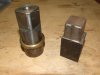
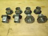
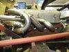
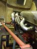
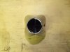
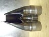
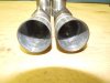
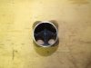
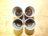
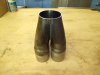
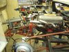
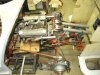
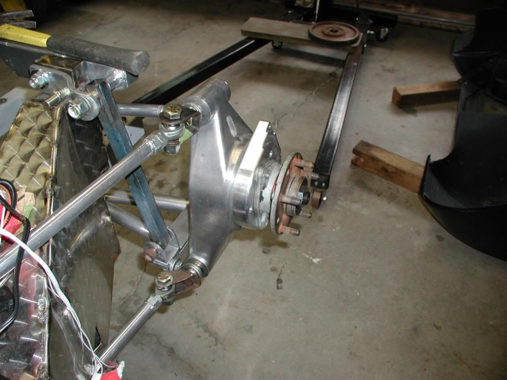
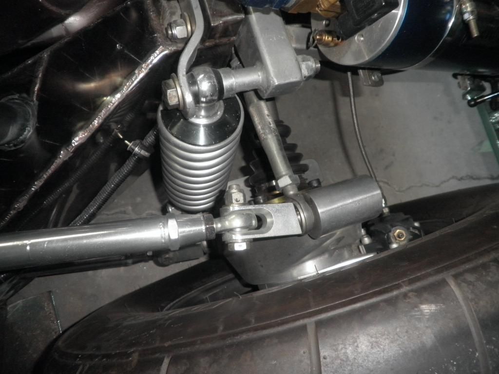
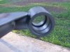
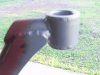
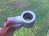
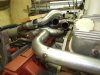
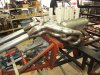
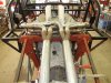
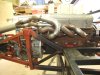
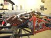
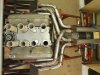
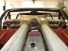
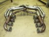
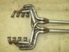
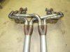
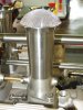
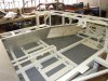
I noticed on your last two post that you have the stock trailing arms from RF. The guys at then race shop that made my headers noticed that my setup was much like yours. They suggested to change over the Delrin bushings for rose joints on both ends, and to go to a beefier link. This makes them adjustable on both ends. The Delrin units will work well on the street but will be stressed on the track.They say it makes the ride harsher, but I can't tell it affects the ride that much. If you plan to track the car you may need larger(stiffer) pieces. Mine are 1 1/4" tubes. Here is the early upright clevis.