Clayton
Supporter
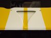
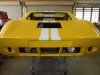
Stripes painted and removed from the booth for the last time :thumbsup:
Had great pleasure in ripping down the booth.
Clayton
Had great pleasure in ripping down the booth.
Clayton

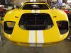
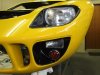
Thanks JimmyLooking bloody good Clayton...nice colour yellow too.
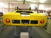
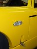
Thanks BrianKudos to you Clayton. Your shut lines are very impressive.
Thanks BobClayton,
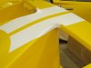
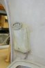
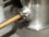
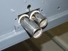
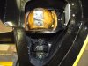
Your work on the small NACA ducts (post #107) inspired me to make one with a round outlet.
See my post #103 on page 6 of "Tornado GT40 in Texas".
-Bob Woods
Thanks BobClayton,
To save me a bunch of time, from now on just assume that every one of your posts will elicit the response "fantastic", "beautiful fabrication work", and "great ideas" from me, and I won't have to respond to every post...
-Bob Woods
Thanks DavidBob, +1
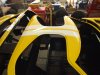
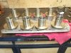
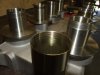
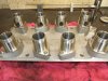
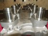
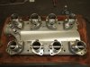
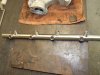
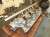
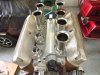
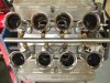
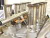
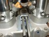
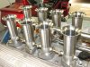
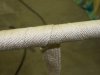
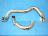
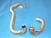
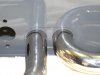
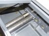
Clayton, incredible work on that injection system and coolant tube. You and your pops have some incredible skills. Really nice stuff...
David