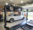
Love the nsx, my supra has been parked since started my 40 build lolI figured I could store the body on my 4 post lift & lift it up out of the way.
Here is what it looks like:
View attachment 138382View attachment 138383
Fran said to hang to doors by the A pillar
View attachment 138384
I supported the spider while resting on the roll bar - let me know if this looks concerning to anyone
View attachment 138385View attachment 138386
My NSX has been relegated to the bottom bunk & is getting to know the new stablemate.
View attachment 138387

You are using an out of date browser. It may not display this or other websites correctly.
You should upgrade or use an alternative browser.
You should upgrade or use an alternative browser.
Rod C's Ohio RCR40
- Thread starter chaffeer
- Start date
Very clean job on the connection of the throttle cable ! What would be the use of a safety switch on a cluctch, I am not familliar with this ?And pedals...I have fabbed up a throttle bracket and a clutch safety switch. I was back and forth, back and forth on the clutch safety switch. At the end of the day I decided to put one in. I currently have the relay mounted to the safety switch bracket. I will use bullet terminals to connect the power to the relay so if something down there fails I can bypass the safety switch & get home.
I will use a toggle ignition switch & a push button start, no key. 3 switches in the left hand panel, 1st is low pressure fuel switch, 2nd is ignition switch, 3rd is push button start. Turn on low pressure fuel, turn on ignition, hit the go button is the plan.
View attachment 150831View attachment 150830View attachment 150829View attachment 150826View attachment 150827View attachment 150828
The safety switch will require the clutch pedal to be in before power is supplied to the starter. Otherwise the car could be in gear, hit the starter & the car will move (if the car starts the car will continue to move). With the safety switch, clutch out = no power to starter button, clutch in = power to starter button.Very clean job on the connection of the throttle cable ! What would be the use of a safety switch on a cluctch, I am not familliar with this ?
A word of caution...
When running your lines through the spine - brake lines, coolant lines, AC lines, etc. - make sure your brake lines DO NOT cross over each other. As you can probably guess, mine did cross each other. Brake lines on the bottom, crossed, caused the coolant pipes to point up toward the rear of the car, not allowing coolant hoses and clamps to fit on the coolant pipes. So disassembly of the entire front end ensued to get the coolant pipes out.
I now have one brake line laying on the driver side of the spine, other brake line laying on the passenger side of the spine, with the bottom coolant tube laying in the middle. I then put in the clutch line, driver side of spine, on top of the bottom coolant tube and below the top coolant tube. I ran my coolant air burb line on the passenger side of the spine, on top of the bottom coolant tube and below the top coolant tube.
Managing the space in the spine is important to getting everything to fit in the tight space. Be sure to stack it all in there without crossing or overlapping anything.
Jeez, it has been a while since I have added to this build log. I have been putting time in on the car over the winter. Let me get this back up to date.
Headers are on. They really make getting to the park plugs impossible. My headers are from RCR, came with my kit. They have two bolt hole patterns, a wide set and a narrow set. I used the wide set, as the narrow set did not allow space to get the headers bolts in. The problem is the wide set makes it impossible to get a spark plug wrench on some of the spark plugs. I will have to remove the headers to get to spark plugs in the future.
.JPG")
.JPG")
.JPG")
.JPG")
.JPG")
.JPG")
Headers are on. They really make getting to the park plugs impossible. My headers are from RCR, came with my kit. They have two bolt hole patterns, a wide set and a narrow set. I used the wide set, as the narrow set did not allow space to get the headers bolts in. The problem is the wide set makes it impossible to get a spark plug wrench on some of the spark plugs. I will have to remove the headers to get to spark plugs in the future.
My fuel system is in and operational. I pull from each tank with a low pressure Faucet duralift pump and fill a swirl pot. A high pressure pump is in the swirl pot to fuel the fuel injection. I do not have the tank caps installed, so I have not added any fuel to a tank yet, but I tested the system with a fuel can and all works OK. Pics show the out and in of each tank, pumps, and return solenoid. The output of the swirl pot goes to the solenoid, which then directs fuel back to the appropriate tank, based on the low pressure fuel pump switch in the dash.
.JPG")
.JPG")
.JPG")
.JPG")
Wiring...I have run a lot of wires. I am using a Holley Sniper 2 fuel injection system, so that adds to the wiring. I am also using a push button start, so that has to be wired up. I am running actual ground wires to the front of the car, to the cockpit and at the rear vs tapping grounds into the chassis. This adds to the amount of wires to run, but I think makes for a more predicable overall wiring set up.
I have a lot of wires in the sponson along with the lower trailing rods and the emergency brake cable. I will eventually put them all in wire wraps to keep them out of the way and tidy. I run the wires along the floor, outbound, to get from the rear to the dash and front of the car. I have been 3d printing grommets for each pass through. So far all seems to be wiring up OK.
My fuses are up under the dash above the drives left knee. Most of what I have wired in so far works, so that is a plus!
.JPG")

.JPG")
.JPG")
.JPG")
.JPG")
.JPG")
I have a lot of wires in the sponson along with the lower trailing rods and the emergency brake cable. I will eventually put them all in wire wraps to keep them out of the way and tidy. I run the wires along the floor, outbound, to get from the rear to the dash and front of the car. I have been 3d printing grommets for each pass through. So far all seems to be wiring up OK.
My fuses are up under the dash above the drives left knee. Most of what I have wired in so far works, so that is a plus!
Remote oil filter - I messed around with some off brand remote oil filter kit that did not work. Lesson learned, spend the money on the better products. I ended up with the Canton parts. I will change it over to AN fittings vs barb & hose clamp (which is leaking). I mounted the remote unit to the rear plate, just behind the rear driver tire. It will make a mess every time I change the oil filter. This is something for me to look forward to.
.JPG")
.JPG")
.JPG")
.JPG")
Coolant - My original plan here did not work. I planned to go from the tank on the firewall to the heater core to the input side of the radiator. I do have a copper tube in my spine to take hot water from the engine to the heater. This did not work, because if the heater is not on, coolant from the tank has no place to go. It dead ends at the heater valve. So for now I have bypassed the heater. I go from the tank back to the water pump. I have a burp line from the top of the radiator back to the tank, a hard 1/4 line that goes through the spine. I do not have an overflow tank in yet. Coolant filled with no problem & currently have no leaks.
The output side of the water pump contacts the firewall. I do not like this situation, but think it will be OK. This is due to the angle of the output neck. I will have to find different thermostat housing to avoid the contact. For now, I am not planning on making a change.
.JPG")
.JPG")
.JPG")
.JPG")
.JPG")
.JPG")
The output side of the water pump contacts the firewall. I do not like this situation, but think it will be OK. This is due to the angle of the output neck. I will have to find different thermostat housing to avoid the contact. For now, I am not planning on making a change.
Radiator Fans - I ordered up a shroud from sendcutsend and it arrived the next day. A little bit of work and fans are in.
My fans will be controlled by the Holley Sniper system, which I can set an on and off temp. With a 180 deg thermostat, I will have them turn on at 190 deg and off at 175. Once they come on, they will likely stay on until the car is turned off. I may add a delay relay to keep them running a few minutes after the car is turned off.
The Holley system will also turn on a dash high temp warning light, probably around 200 deg
..JPG")
.JPG")
.JPG")
Horns - every car needs a loud set of horns. Here you can see the front ground terminal.
.JPG")
My fans will be controlled by the Holley Sniper system, which I can set an on and off temp. With a 180 deg thermostat, I will have them turn on at 190 deg and off at 175. Once they come on, they will likely stay on until the car is turned off. I may add a delay relay to keep them running a few minutes after the car is turned off.
The Holley system will also turn on a dash high temp warning light, probably around 200 deg
.
Horns - every car needs a loud set of horns. Here you can see the front ground terminal.
It runs! I have started the car. I had a little hiccup because the distributor was not plugged in. Once it was plugged in, the car fired right up. No major leaks. I had a problem with one of my transaxle bolts being too long and rubbing against the flex plate. If you are using the RCR adapter plate between a Ford 302 black and a Porsche G96 transaxle, 3 or 4 of the transaxle mounting holes go directly through to the flex plate. Be careful with the length of these bolts. I sanded down all of then to ensure no contact with the flex plate.
It feel great to reach the starting milestone. The car is very loud with straight pipes. I am going to try the spiral baffle inserts 1st before I start looking for full on exhaust.
I have a video, will have to do some investigating to get it posted.
It feel great to reach the starting milestone. The car is very loud with straight pipes. I am going to try the spiral baffle inserts 1st before I start looking for full on exhaust.
I have a video, will have to do some investigating to get it posted.
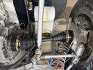
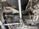
Axles - I had read and heard the axles RCR supplies with the kit do not have enough angle to allow full suspension drop. Well, I guess I misunderstood these warnings. I installed the axles with my car up on stands. One axles I turned and turned to tighten the CV joint bolts. It sure did seem to turn hard. Well, when the CV boots popped off of the CV joint I knew I had a problem. Why did they turn so hard? Because I was bending the boot flange due to the angle of the axle.
.JPG")
.JPG")
.JPG")
.JPG")
.JPG")
.JPG")
.JPG")
.JPG")
.JPG")
I removed both axles, took them apart, removed the flanges, cleaned everything up, repacked the CV joints with grease, and reassembled, with larger CV boot flanges on the axle side. I ordered the flanged and boots from Dan's Performance Parts
flange part number #14-501105FS
boot part number #14-501105
I do not know if they are going to work. I do know to now limit rear suspension travel when I lift the car. I have them installed and mounted. At least I can now rotate the rear wheels without the boot coming off and getting a workout. The wheels now rotate as expected, without significant force required.
Last edited:
.JPG")
.JPG")
.JPG")
.JPG")
.JPG")
.JPG")
yes, axle boots and flanges are a problem (known to the Porsche racing division as well). As are the CV joints themselves when high angularity is an issue. The latter determine the real limit. My rear wheels are difficult to turn when hanging freely. So I refrain from trying. I went with the special ``high-performance" boot/flange set from the Driveshaft Shop. CV joints and boots have been discussed on this forum before ! (High-angularity CV joints are known to/in the off-road community but usually for engines with less torque and/or for use on slippery surfaces. )Axles - I had read and heard the axles RCR supplies with the kit do not have enough angle to allow full suspension drop. Well, I guess I misunderstood these warnings. I installed the axles with my car up on stands. One axles I turned and turned to tighten the CV joint bolts. It sure did seem to turn hard. Well, when the CV boots popped off of the CV joint I knew I had a problem. Why did they turn so hard? Because I was bending the boot flange due to the angle of the axle.
View attachment 151719View attachment 151717View attachment 151716View attachment 151715View attachment 151728View attachment 151729View attachment 151731View attachment 151732View attachment 151733
I removed both axles, took them apart, removed the flanges, cleaned everything up, repacked the CV joints with grease, and reassembled, with larger CV boot flanges on the axle side. I ordered the flanged and boots from Dan's Performance Parts
flange part number #14-501105FS
boot part number #14-501105
I do not know if they are going to work. I do know to now limit rear suspension travel when I lift the car. I have them installed and mounted. At least I can now rotate the rear wheels without the boot coming off and getting a workout. The wheels now rotate as expected, without significant force required.
``Welcome to the club!"
Lee Patterson
Supporter
FWIW, the SPF axles come with two different CVs - a plunging CV (which mounts to the ZF) and a non-plunging CV which mounts to the wheel hub. The plunging CV moves and deflects a lot more than the non-plunging end. Ron McCall instructed me to mount them this way.
Do yours have a plunging end?
Do yours have a plunging end?
Its a complicated situation to deassemble the headers before to access to the sparkplugs, the sparkplugs are not simple accessories and access for a regular yearly change or to check compression or to vent the cylinder in case of bad starting conditions is often mandatory. Why to not consider a more conventionnal header.Jeez, it has been a while since I have added to this build log. I have been putting time in on the car over the winter. Let me get this back up to date.
Headers are on. They really make getting to the park plugs impossible. My headers are from RCR, came with my kit. They have two bolt hole patterns, a wide set and a narrow set. I used the wide set, as the narrow set did not allow space to get the headers bolts in. The problem is the wide set makes it impossible to get a spark plug wrench on some of the spark plugs. I will have to remove the headers to get to spark plugs in the future.
View attachment 151684View attachment 151683View attachment 151682View attachment 151681View attachment 151680View attachment 151679
You are correct, it will be a pain in the a$$ to remove the headers to get to the plugs. It big now all assembled, so it will have to be taken apart at some point in time. When I do it, I will take a look at the headers to see how they can be modified to allow access to the plugs. I am confident I will only have to remove the headers to get to the plugs one time, the next time.Its a complicated situation to deassemble the headers before to access to the sparkplugs, the sparkplugs are not simple accessories and access for a regular yearly change or to check compression or to vent the cylinder in case of bad starting conditions is often mandatory. Why to not consider a more conventionnal header.
I am by no means an expert on cv joints. I would not have even described myself as a novice. With that said I did disassemble and reassemble both of my axles, 4 cv joints, to change the inner flange and boot on all 4 ends. Maybe I am now a senior novice?FWIW, the SPF axles come with two different CVs - a plunging CV (which mounts to the ZF) and a non-plunging CV which mounts to the wheel hub. The plunging CV moves and deflects a lot more than the non-plunging end. Ron McCall instructed me to mount them this way.
Do yours have a plunging end?
From what I could see the axles, provided by RCR for their GT40 kit are identical on both ends & both sides of the car.
Lee Patterson
Supporter
All you want to know about 930 plunging vs. non-plunging CVs.
Thank you for the informative video. All of the joints provided by RCR are the plunging type.FWIW, the SPF axles come with two different CVs - a plunging CV (which mounts to the ZF) and a non-plunging CV which mounts to the wheel hub. The plunging CV moves and deflects a lot more than the non-plunging end. Ron McCall instructed me to mount them this way.
Do yours have a plunging end?
Similar threads
- Replies
- 17
- Views
- 3K