
- Forums
- GT40 Replica Manufacturers' Corner
- RCR Forum - RCR40/SLC/917/Superlite Aero
- The SLC Clubhouse
You are using an out of date browser. It may not display this or other websites correctly.
You should upgrade or use an alternative browser.
You should upgrade or use an alternative browser.
Johan
Supporter
I have a tendency to do a lot of things all over the car, so now I`m trying to focus on one thing at a time.
Next couple of weeks it will be the front only and first up was lighting.
I started with leveling the front against the garage door to fabricate a flat/level surface to mount the headlights to. 4 cutting disc was used to accomplish this.Tape and release agent on the discs and then FG bondo, when cured 3 layers of FG mat.
The mounts was made of 3mm aluminium and then I installed rivnuts backwards and it just happend that the adjusting springs snugfits over the rivnuts. Some filletine wax and tape/release agent was used.
FG bondo was used to fixate the alu mounts to the clam. Excess bondo to be cut of just when it starts to cure and when fully cured they were secured with 4 M5 bolts, tapped and glued. They will never come off again, even if I want to.
Johan
Supporter
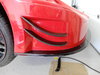
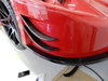
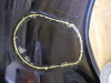
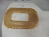
The turn/blinkers that came from RCR is not E-marked and can`t be used in Europe, I got hold of 60mm LED turn sig lights and they didn`t fit, the stock mounting hole is less, so cut a 60mm hole an that meant nothing was left of the material.
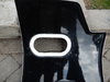
Same procedure again, taped up the blinker applied release agent and bonded it to the body, when cured I sanded it smooth and added 4 layers of FG mat.
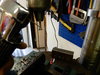
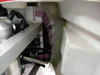
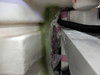
I routed the wiring in electrical pvc tubing and added two whetherpack connectors just above the hinge pivoting point.
The front electrical system is now completed exept for the horn and fog lights. (I glassed over the brake cooling ducts for fog lights)
Electrical pvc tubing is used to route the wires and whetherpack connectors at the hinge pivot point.
https://imgur.com/KNmy4Pw.jpg
Same procedure again, taped up the blinker applied release agent and bonded it to the body, when cured I sanded it smooth and added 4 layers of FG mat.
I routed the wiring in electrical pvc tubing and added two whetherpack connectors just above the hinge pivoting point.
The front electrical system is now completed exept for the horn and fog lights. (I glassed over the brake cooling ducts for fog lights)
Electrical pvc tubing is used to route the wires and whetherpack connectors at the hinge pivot point.
https://imgur.com/KNmy4Pw.jpg
Last edited:
Johan
Supporter
More pics.
Most of the wiring and brake hoses are hidden.
Most of the wiring and brake hoses are hidden.
Very nice, I have to remember this when I am getting to this point..
Johan
Supporter
The reason is the E-marking again. I will never get it through inspection with DOT marking only. Guess it’s the same over there, you must have DOT. Funny thing is I got hold of the E-marked Hella in the US.
I have the RCR head light mount/cups, but they were such a bad fit I elected to make new ones instead.
I have the RCR head light mount/cups, but they were such a bad fit I elected to make new ones instead.
Johan
Supporter
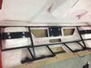
I started with the rear clam today, made a steel frame in 20mm*20mm tubing. Added two more mounts on the lower factory steel tube, and four mounting plates further up.
It might look a little overkill, but I`m planning to remove the "bumper" part of the clam and have the diffuser mounted separatly, just haven`t decided yet.
The frame was mounted in a bed of FG bondo, that way I don`t have to be too acurate with the fit of the mounts.
Got an idea last night when my "sunshine" was baking a cake and sprinkled whipped cream on it, I thought that plastic bag sprinkler could come in handy, so I gave it a try and it worked fantastic.
In stead of putting the bondo on the FG and then placing the frame on it, I installed the frame first and then pressed/sprinkled the bondo in the cavities in between the frame and clam. It goes much faster that way and you don`t have to risk the bondo starts to cure before you`re done.
Next up will be the rear lights and the rear electrical harness.
I have also made a new forward hoop for the roll cage, it is 3"/ 75mm wider then the factory, more of that in the next post.
Johan,
I looked at the beginning of your build and it appears you are using the Graziano trans. I am as well. I also fabricated a steel brace for the rear clam. It makes the rear clam very solid so you can open and close it from one side with ease. Mine bolts on. Notice I had to remove the center section of the bottom tube to clear the Graziano. Will your brace clear the rear of the transaxle?
I also intend to remove the fiberglass “rear bumber looking thing” and fabricate an aluminum diffuser further forward so it does not stivk out as much as the rear “bumper” like Rumbles did in his build. I am in the planning stage so nothing to show at this time.
I have enjoyed reading your build and should start a build post of my own. However, I do not type very fast.
Attachments
Johan
Supporter
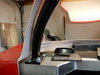
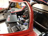
A new forward roll hoop is in place and welded. It is 70mm wider than factory, much better forward vision. Could have made it another 10mm wider but it was quite difficult because the radius isn`t constant along the A-pillar.
I will fabricate new A-pillars when I get to the interior. The forward mounts is made of 10mm steel plate milled down to 8mm and a 4mm stainless steel under the aluminium frame, and the hoop itself is made out of 4mm Docol R8 tubing.
I will fabricate new A-pillars when I get to the interior. The forward mounts is made of 10mm steel plate milled down to 8mm and a 4mm stainless steel under the aluminium frame, and the hoop itself is made out of 4mm Docol R8 tubing.
Attachments

Last edited:
Johan
Supporter
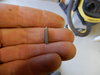
The new Canards from Henry Nickless is in place as well. I made small "markers" out of M4 screws, put them in a pedestal drill and cut them with a high speed grinder at 45*, then inserted them in the canards and pressed them to the front clam to get a mark where to drill the holes. The fit was next to perfect, just some minor sanding.
But as you can see in the last picture, the carbon fiber is not laid in the same direction on the upper vs lower canard. The left side is good.
But as you can see in the last picture, the carbon fiber is not laid in the same direction on the upper vs lower canard. The left side is good.
Attachments
Last edited:
Johan
Supporter
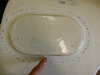
I cut out the lids in the front inner fenders, not completely though, I left about 2mm in four places around the perimeter just enough to keep it in place then pressed filletine wax in the cut and taped up the lid on the back and some release agent. Then I fiberglassed a mounting flange on the back side and when cured I cut the last millimeters off. The lids will be screwed in place with FG rivnuts ”a la CamT”
Attachments
Last edited:
Johan
Supporter
I also made a mounting flange in the rear of the spider to mount a close out panel later on and to stiffen the spider somewhat. I did this with the spider mounted correctly. If not, I will risk the rear clam doesn’t fit perfectly, and who knows, maybe the front clam and windshield as well. Fiberglass is a odd material.
Attachments
Last edited:
Joel K
Supporter
A new forward roll hoop is in place and welded. It is 70mm wider than factory, much better forward vision. Could have made it another 10mm wider but it was quite difficult because the radius isn`t constant along the A-pillar.
I will fabricate new A-pillars when I get to the interior. The forward mounts is made of 10mm steel plate milled down to 8mm and a 4mm stainless steel under the aluminium frame, and the hoop itself is made out of 4mm Docol R8 tubing.
Nice work Johan, my SLC is on order and that is one of the chassis mods I asked Fran and team to do. To make the roll hoop closer to the A-Pillars. All in all your build is coming along so well and I am amazed how quickly you are able to complete each step

Johan
Supporter
One thing I’ve noticed when mounting the body, be careful how to mount it on the longitudinal axis. I read a lot of build threads before starting my own build and several suggested to push the spider forward until the rear cupholders hit the rear aluminium crossmember. This all looked good in the beginning (wheel was centered in wheelwells), but when I got further in the build I discovered a lot of signs that it should be about 6-8mm further back.
The problems are: The inner tub can’t really go that far forward (the front floor cross members put a stop to this) it works after some mods but would be better 8mm back, the rear J-hinges must be ”opened up” to be able to open the rear clam, the upper part of the tub must be grinded more than nessesary to clear the fwd roll hoop among other things.
I know FG is a ”living” material but they are all molded in pretty much the same mold so I think this goes for all the bodies. What I’m saying is just don’t start to bolt down the spider first thing when all lookes fine, instead fixate it with a couple of bolts and clamps it it down and then fit all inner panels and hinge the front and rear clam to final position. I think the end result will be better.
The above is valid for the street tail.
Similar threads
- Replies
- 10
- Views
- 2K
- Replies
- 3
- Views
- 1K