SLC 007 Dave Lindemann

Dave Lindemann

Lifetime Supporter
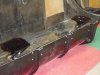
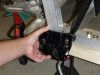
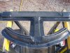
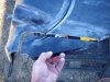
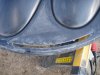
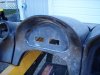
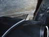
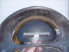
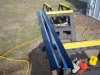
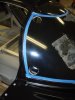
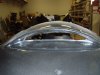
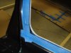
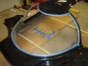
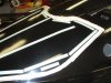
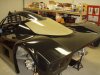
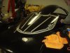
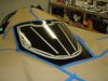
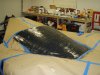
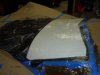
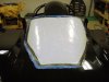
Here's some more info on the rear hinge. Fran/RCR did an excellent job designing it I think. The rear hinge plates mount to existing bolt points on the rear of the chassis. I just need to buy some longer bolts. The plates have slotted openings to allow for some adjustment of the clip. Pretty cool. All I need now is time........

Dave L
 

Attachments

  • Rear Clip Hinge Placement on Chassis.jpg
    Rear Clip Hinge Placement on Chassis.jpg
    39.8 KB · Views: 502
  • Rear Clip Hinge Plates on Body.jpg
    Rear Clip Hinge Plates on Body.jpg
    50.2 KB · Views: 540

Dave Lindemann

Lifetime Supporter
Re-awakening my old build thread....moderators - this probably should be moved to the SLC Build Log section.

While I'm not working on the car yet due to my Lotus project, I am constantly thinking about the SLC. Especially after my recent visit to RCR and watching Stacey put an SLC together on Gearz.

I'm wondering what SLC builders with LS engines are doing for the exhaust?

I have an LS3 with stock manifolds. I've spoken to Fran and he suggested buying a set of LS7 manifolds because they flow better. So, I just won a set of new take offs on eBay. I'm planning on rear exit exhaust and no cats. Are the manifolds the way to go or would it make more sense to go with headers. If so, where are you getting them from or are you making them yourself?

My understanding is that Fran is working with someone to come up with an exhaust system but I see a number of people doing their own.

All opinions and advice is appreciated.
Regards,
Dave L
 
Dave,

One of the better descriptions/photos of using stock LS7 is in Cam's build log. I am having Roberto build a set of headers for my LS7, rear exit style.

Doc
 
Dave, the LS7 exhaust manifolds flow as good or better than any aftermarket header
commercially available. I think Fran is using them on the race car as well. The "J" bends required will make for some interesting fabrication to the exhaust large opening. I believe RCR has some exhaust flanges available to mate to the LS7 manifolds. I am fabricating mine similar to what you have described. Don't forget you will need two O2 sensor weld bungs. One on each side.
 
I'm curious why more people aren't side porting the exhaust? Tell me why I'm wrong here, but it seems:

~A lot less fabrication.
~Less materials to buy.
~Less pipe means less to protect from heat.
~Costs less.

Edumacate me.
 
Yes to all of the above, but:
Heat source closer to some fuel system components like a swirl tank, etc.
Very loud with only about a foot to fit mufflers (if that). Okay for race car. Although I'm fabricating a rear exit system, I'm also adding a couple of aluminum panels to the chassis tubes from the backside of the 2x6 rear crossmember to the forward side of the upper shock rocker areas. Both sides. Relieved for weldments and coolant tubes, etc. It will make a great heat shield, especially if gold foil is used on the inner side. Can hang filters, etc. from it too. One compound bend is required, PITA to make.
 
Just a side note to my last post...
If you use the side exhaust, lay it out completely before finalizing your fuel system. I failed to do this and it's the primary the reason for my rear exhaust terminus. Can we say "rework"...All will be well in either scenerio.
 

Dave Lindemann

Lifetime Supporter
Doc - Thanks, I'll take another look through Cam's build thread.

Jack - Thanks for the feedback on the LS7 manifolds - that's basically what Fran told me. I'll have to check with Fran to see if he has any flange plates available. I have no welding or exhaust pipe forming talents so I'll have to have a shop do the fabrication when I get to that point. The oxygen sensor bungs came with the engine and I just today purchased the O2 sensors.

Ben - I agree with Jack regarding the side vs. rear exhaust. For a street car like mine I prefer less noise (larger mufflers can be used with the rear exit) and I simply like the look of the pipes coming out the back of the car.

Regards,
Dave L
 

Dave Lindemann

Lifetime Supporter
Moderators - feel free to move this thread.

I actually had some time to work on the SLC today and even though I wasn't able to accomplish much - I had fun - and that's what it's all about in my book.

My hope was to finish opening up all of the body openings/fiberglass cutting since the weather was decent. That won't last much longer! I spent quite a bit of time on the dash cutting out the roll bar openings, defroster vent openings, and cutting off the back of the Digidash recess and cutting the connector openings. I cut off the Digidash recess to be able to recess the unit deeper into the dash as others have done. I also cut the defroster vent openings in the under-dash air plenum and cut the single-piece side skirt into two pieces. I taped off and drilled the corners for the windshield opening but I wasn't able to complete the cut because I need another set of hands to move the spider outside of the shop (want to minimize dust).

Another small step forward.....

Regards,
Dave L
 

Attachments

  • SLC Dash Air Plenum Cut-outs.JPG
    SLC Dash Air Plenum Cut-outs.JPG
    150.6 KB · Views: 360
  • SLC Dash Cut-out for Roll Bar Gap.JPG
    SLC Dash Cut-out for Roll Bar Gap.JPG
    157 KB · Views: 326
  • SLC Dash Defroster Vent Cut-out.JPG
    SLC Dash Defroster Vent Cut-out.JPG
    155 KB · Views: 322
  • SLC Digidash Cut-outs.JPG
    SLC Digidash Cut-outs.JPG
    147.3 KB · Views: 355
  • SLC Dash Cut-out Around Roll Bar.JPG
    SLC Dash Cut-out Around Roll Bar.JPG
    160.7 KB · Views: 316
  • SLC Digidash Cut-out.JPG
    SLC Digidash Cut-out.JPG
    159.8 KB · Views: 319
  • SLC Dash Installed.JPG
    SLC Dash Installed.JPG
    161.9 KB · Views: 379
  • SLC Sideskirts Cut.JPG
    SLC Sideskirts Cut.JPG
    150.9 KB · Views: 315
  • SLC Windshield Cut-out Corner Holes Drilled.JPG
    SLC Windshield Cut-out Corner Holes Drilled.JPG
    168.1 KB · Views: 328

Dave Lindemann

Lifetime Supporter
More baby steps.......
 

Attachments

  • Windshield Rough Cut.JPG
    Windshield Rough Cut.JPG
    155.4 KB · Views: 313
  • Windshield Cut Out Finished.JPG
    Windshield Cut Out Finished.JPG
    161.8 KB · Views: 279
  • Windshield Edge Close-up.JPG
    Windshield Edge Close-up.JPG
    158.6 KB · Views: 273
  • Scoop Rough Cut.JPG
    Scoop Rough Cut.JPG
    150 KB · Views: 299
Hi Dave, I can't see why RCR don't cut these appertures out for people. I know it's not rocket science but it would be so easy for the factory to do it.

Hurry up Dave I need to see more posts
Cheers
 
Seems to me like it would help the fiberglass hold its form and limit any sag if it were to sit for a period of time. That might not be an issue but if it could be it would be a good idea to ship it uncut.
 

Randy V

Moderator-Admin
Staff member
Admin
Lifetime Supporter
Nice to see you're back in action on the car Dave! :thumbsup:


Seems to me like it would help the fiberglass hold its form and limit any sag if it were to sit for a period of time. That might not be an issue but if it could be it would be a good idea to ship it uncut.

This is what I was also thinking. Having had the top of my GT40 sag (even with the windshield taped in place) while it sat in my trailer for a couple of months.. I would get some support under that structure fairly quickly or pay the price later when trying to get everything to align properly.
 
Yah, I had it happen to a fiberglass hood for one of my mustangs that I leaned up against the wall over a summer. I had to use a heat and weight trick to get it back to shape.
 

Dave Lindemann

Lifetime Supporter
Thanks guys. The spider won't be off the chassis for long and I do have the side pods secured together at the correct chassis width. I haven't noticed any sag but it's possible. I typically have the spider on the chassis and the doors set in place but I haven't set the windshield - of course until now the opening hasn't been cut. The fiberglass has had plenty of time to fully cure - it was delivered 4 years ago!

Randy - I just received a note from Dave E and it sounds like the Europa body will be finished at the end of the year - I can't wait!

Dave L
 

Dave Lindemann

Lifetime Supporter
Arts & crafts day......

I decided a while ago that I'd like to use a fiberglass or carbon fiber rear window in place of the stock plexi-glass. RCR offers GRP and CF rear windows for $300 and $550, respectively though you'd have to confirm the prices with Fran. However, I like little projects like this so I decided to make my own mold. Then I can make rear windows for minimal cost and figure out a design that I like. The first step was making the mold.

A good friend came out to help me yesterday and we worked into the evening - don't expect to make a mold this size in an hour or two..... My friend has a lot of experience building composite structures for experimental aircraft and his input was invaluable. Here are the steps we used for making the mold:

1. Use the "race tail" window and body because it's the full window and the body contours are easier to pull a mold from. Note that the window for the street tail is identical to the race version except there is a section cut out at the bottom of the window.
2. Fit the spider and tail to the chassis to ensure the body contours are correct.
3. Use 3M double sided foam (thin) tape to adhere the plexi-glass to the fiberglass. Use extra tape where the "wings" of the window attach because they like to spring out a bit.
4. Use modeling clay to fill the gap between the plexi and the body and where the forward part of the rear clam rests on the spider.
5. Apply and buff off 6 coats of parting wax - on the plexi and surrounding body panels - well beyond the window area.
6. Tape off the window area with heavy kraft paper. Note - I used blue painters tape and if I had to do it over again I'd use clear packing tape because the combination of PVA and resin soaked into the tape and softened the glue allowing some resin past the tape/kraft paper.
7. Spray apply a good coat of polyvinyl acetate (PVA). We used a Preval sprayer but found that we needed to dilute the PVA about 50/50 with water to achieve an acceptable spray.
8. Find a suitable surface to do the lay-up. We used the floor and covered it with a large plastic garbage bag that we cut open along the side and bottom.
9. The mold lay-up we used was 3 layers of 7.5 oz. woven cloth, 1 layer of 2 mm Baltek Coremat and 2 layers of mat. The mat was the final lay-up layer that was applied to the surface of the window to prevent bleed-through of the coremat or woven cloth pattern onto the surface of the mold. All layers were pre-cut about 2" larger than the window.
10. Resin - we used AdTech Probuild Marine Epoxy - and lots of it. We were going for a wet lay-up to better ensure that the surface of the mold would be as smooth as the plexi. We went through a full gallon of resin and a quart of AdTech Probuild Marine Epoxy Hardener.
11. Wetting of the lay-up was done on the floor in layers. Once all layers were fully wetted out we lifted the plastic sheet and lay-up onto the window and smoothed it onto the window with our hands paying particular attention to the perimeter of the window to ensure the mold will have a clearly defined cut line for the molded part.

By this morning the epoxy had hardened and I was able to peel back the plastic garbage bag and pull off the kraft paper. We did have some excess resin get past the painters tape but most of it peeled/chipped off pretty easily. I plan to leave the mold cure on the window for a week. Then I'll fabricate a mold support to ensure it will keep the correct shape and then pull it off the window and see how it turned out.

So far my total cost for all of the mold materials and supplies is ~$250.

Here are some pictures:
 

Attachments

  • New Rear Window - Double Sided Tape in Place.JPG
    New Rear Window - Double Sided Tape in Place.JPG
    154.1 KB · Views: 294
  • New Rear Window - Plexi in Place.JPG
    New Rear Window - Plexi in Place.JPG
    138.1 KB · Views: 318
  • New Rear Window Modeling Clay in Place.JPG
    New Rear Window Modeling Clay in Place.JPG
    155.3 KB · Views: 306
  • New Rear Window Polished and Taped.JPG
    New Rear Window Polished and Taped.JPG
    156.1 KB · Views: 309
  • New Rear Window Mold Lay-up.JPG
    New Rear Window Mold Lay-up.JPG
    153.1 KB · Views: 326
  • Rear Window Mold - Pulling Back the Lay-up Plastic.JPG
    Rear Window Mold - Pulling Back the Lay-up Plastic.JPG
    153.9 KB · Views: 301
  • Rear Window Mold on SLC.JPG
    Rear Window Mold on SLC.JPG
    135.3 KB · Views: 302

Dave Lindemann

Lifetime Supporter
Rear Clam Flex When Lifting (could apply to the front as well):

I know the rear clam flexes quite a bit if one attempts to lift it from one side and I believe that is why so much of the "window" cutout remains. I'm just curious if anyone has considered - or perhaps already tried vacuum bagging foam core to the underside of the clam?

I'm thinking about doing this across the forward edge of the clam just behind where it rests on the spider. A friend of mine used to build composite aircraft and he showed me a panel with a single layer of glass applied to both sides of a foam core and the rigidity of the panel was amazing. I'm thinking that strategically placed foam core could virtually eliminate panel flex without adding hardly any weight.

Dave L
 

Randy V

Moderator-Admin
Staff member
Admin
Lifetime Supporter
Hi Dave,

I am a bit concerned about his with my GT as well, but I think that the addition of pneumatic support struts will help in reducing..

Thoughts?
 
Back
Top