Howard Jones
Supporter
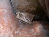
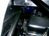
Yes, this is part of the continuous air bleed system. A line runs from the T back to the header tank.

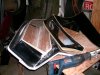
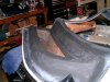
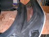
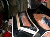
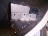
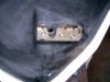
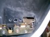
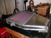
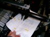
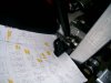
The second is the piece to be cut out and the last couple are of the door after having the interior piece timed and fiber-glassed in place.
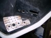
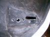
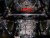
Next big thing is I will need to take the center body section off the car and glass in the lower hedge backing plates.
I remember F1 had all sorts of weird names for their wild aerodynamic appendages: "barge boards," "fences". What is a "hedge system"? Is it something having to do with the aerodynamics?The intention is to carry the weight of the bodywork when down, closed, in place and to try and keep the loads off the hedge system.

")