Nice photo of COTA Howard! We have a batch of grandstand seats every year near corner 12 (at end of long straight) and can see action through corner 15. 12 has been a great overtaking site each year for F1. And, you get to see the Ferrari Challenge guys mash up there cars often! BTW....Happy Texas Independence Day! (March 2, 1836).....:thumbsup:

- Forums
- GT40 Replica Manufacturers' Corner
- RCR Forum - RCR40/SLC/917/Superlite Aero
- The SLC Clubhouse
You are using an out of date browser. It may not display this or other websites correctly.
You should upgrade or use an alternative browser.
You should upgrade or use an alternative browser.
SLC 24 Howard Jones
- Thread starter Howard Jones
- Start date
Howard..
Please provide a few comments on the use of the snap vents for your side windows. I assume that they weren‘t effective and that is why you cut larger openings afterwards?Or do they work in conjunction with eachother?
Also, what is your future plan for the sway bars? Are they pretty spot on or will you change them?
Great build....
Sorry.. I‘m typing from a hotel PC in Japan and thus the text is jacked up...I‘ll be back on my build soon.. Work is getting me a bit bogged down.
Howard Jones
Supporter
The snap vents do work. I would put some small drops of liquid dish soap on a few places on the side windows and drive the car at about 40-50 mph and see where you get the best surface airflow on the windows. Where I have mine work but lower or higher might work better. It's hard to guess airflow around the A pillar.
The bigger square holes are to put my hand out for track signaling and to evacuate hot air sitting still on the grid. They generally do not intake much air at speed. They are in a low pressure zone.
My car does not have AC
Sway bars, So far I am not going fast enough (only one track weekend) to evaluate. The car hasn't been driven at the limit of adhesion so it's very hard to tell what's going on other than it has huge grip. That will change, but for now I wouldn't put them on a street car. You can't (shouldn't) drive one of these that hard on the street IMHO. If it gets away from you at these grip levels, you're are going to hit something VERY hard.
If you want to talk send me a PM and I'll forward my phone #.
Howard Jones
Supporter
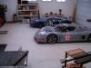
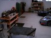
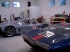
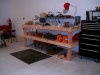
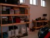
So......It's been awhile since I have posted anything. I've been busy moving and getting my new home done. That has pretty much been finished. So on to the shop. Here's some first pics of my garage/shop, the girls new home.
I built some wooden shelves and benches and am about ready to build a steel welding bench. Still no refrigerator and stereo setup.
I built some wooden shelves and benches and am about ready to build a steel welding bench. Still no refrigerator and stereo setup.
Attachments
Howard Jones
Supporter
Aaron, they are made from 1/8 alum and yes the mounts are alum angle as well. See post #717 for some better pictures. I think I had a little to say about design in and about that post also.
Last edited:
Congrats on the shop, Howard. Very nice looking. Glad to see the move from CA has been completed.
Was at the SVRA races at COTA this weekend supporting a couple of the guys from the Corvette club. Great racing until it rained out the track Sunday afternoon.
Give me a call sometime - I'd love to see your cars/shop.
John Dewey
Was at the SVRA races at COTA this weekend supporting a couple of the guys from the Corvette club. Great racing until it rained out the track Sunday afternoon.
Give me a call sometime - I'd love to see your cars/shop.
John Dewey
")
Howard Jones
Supporter
JD, could you PM me your Ph#. I can't find it anywhere. I send mine back also.
Howard Jones
Supporter
Double post....sorry
Last edited:
Howard Jones
Supporter
So here's the latest. I have ben driving around the neighborhood a bit playing with the brake bias. The idea was to get an idea on just how much range I had. I pretty much know I will need to reduce the size of the masters but it's been a year since I last drove the car and I was really interested in some kind of base line foot to peddle effort.
Well I am right. Just not enough brake line pressure to the calipers is my guess and along with some calculations I think I am in the 700-800 PSI range for caliper clamping pressure. This is at stand on the peddle max effort foot pressure. I will fix that for sure.
BUT in the process I have come to the conclusion that the high water temps I saw at the track are a problem with system flow volume. Even with the thermostat completely removed I just didn't think it was moving enough water. So I took the water pump off the car and found that the low cost Weiland pump I have isn't going to cut it. Very small internal cavity and passages along with a bit of casting blockage. I could have ported it out but I think I should do this right the second time.
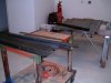
Therefor I will install a Davies Craig electrical pump. These are a brushless design that really has become the state of the art in DC high torque pumps. I added a attachment that explains Brushless DC motors for your entertainment.
I also have included a picture of how the mechanical pump is replaced with a manifold. The picture isn't my car because it would be difficult to photograph in place, but it's the same parts on another SBC like mine.
More to come on this as I do the conversion.
https://www.youtube.com/watch?v=bCEiOnuODac
Well I am right. Just not enough brake line pressure to the calipers is my guess and along with some calculations I think I am in the 700-800 PSI range for caliper clamping pressure. This is at stand on the peddle max effort foot pressure. I will fix that for sure.
BUT in the process I have come to the conclusion that the high water temps I saw at the track are a problem with system flow volume. Even with the thermostat completely removed I just didn't think it was moving enough water. So I took the water pump off the car and found that the low cost Weiland pump I have isn't going to cut it. Very small internal cavity and passages along with a bit of casting blockage. I could have ported it out but I think I should do this right the second time.
Therefor I will install a Davies Craig electrical pump. These are a brushless design that really has become the state of the art in DC high torque pumps. I added a attachment that explains Brushless DC motors for your entertainment.
I also have included a picture of how the mechanical pump is replaced with a manifold. The picture isn't my car because it would be difficult to photograph in place, but it's the same parts on another SBC like mine.
More to come on this as I do the conversion.
https://www.youtube.com/watch?v=bCEiOnuODac
Attachments
Nooooooo Not a Davies craig...... Prefer
Meziere Enterprises.
The Davies did not work well on a Silver SLC with 360 chevy. The Meziere we ran in the Blue Miss worked great no issues. They even make a stand alone belt driven pump that you can mount like a dry sump pump off to the side.
Good luck
Meziere Enterprises.
The Davies did not work well on a Silver SLC with 360 chevy. The Meziere we ran in the Blue Miss worked great no issues. They even make a stand alone belt driven pump that you can mount like a dry sump pump off to the side.
Good luck
So......It's been awhile since I have posted anything. I've been busy moving and getting my new home done. That has pretty much been finished. So on to the shop. Here's some first pics of my garage/shop, the girls new home.
I built some wooden shelves and benches and am about ready to build a steel welding bench. Still no refrigerator and stereo setup.
Does your new garage still look this new Howard? :laugh2:
Howard Jones
Supporter
Don, do you know which DC pump was on the silver SLC ? What was the issue and where was it mounted. I am a bit on the way with the DC at this point but I could return the pump and still use the manifold if it really is a problem.
Howard Jones
Supporter
I bought the 55GPM alum housing pump. The silver SLC may have had the 80GPM plastic version. I think I will complete the install and see how it goes, Thanks for the information. Now I at least know what to do if I need a alternative.
We will know one way or another.
Again Thanks Don, your friend Howard.
We will know one way or another.
Again Thanks Don, your friend Howard.
Howard Jones
Supporter
My mistake. I bought the EPW 150.
http://daviescraig.com.au/product/e...70/ewp150-alloy-lcd-controller-combo-12v-8870
It has a flow rate of 150 gpm. More importantly it maintains 5-6 psi up to about 60 gpm and at 100 gpm it still holds up to about 3 psi. The best plastic one, EPW 115 begin to loose ground to the 150 at about 4psi where it will flow about 75 gpm and at 100 gpm it is down to 2 psi.
High flow rate and being able to hold system pressure at a high rate of flow is the key IMHO. This is where the mechanical pumps fail. At the high end of the engine rpm range the pump impeller is experiencing cavitation. The simply can't be reved past about 4000 rpms and not begin to cavitate.
Assuming a 6 inch crank pulley and a 4 inch water pump pulley you have the impeller turning at more than 10000 rpms with a 7K engine speed. Even if you reverse the pulley sizes and use the 4 inch on the crank and the 6 inch on the pump you still have impeller speeds above 4500 rpms @ 7K. And when you slow down the water pump to around 4000 rpms or less then crake pulleys sizes get smaller than practical and water pump pulley sizes get bigger than available. Its the high end that kills the efficiency of mechanical pumps. But mostly it's the rpm range of road race cars that's the problem. Mechanical pumps just don't work well at both ends of the range. Then you try and do a dual use, street/track, and things really get complicated.
The other thing than makes a lot of difference in the application of electric verses mechanical pumps is placement. The pump should be mounted at the location where the inlet is as low as possible to the volume of water. Easy to do with the electric pump. Were as the mechanical pump is on the front of the engine and above the majority of the water volume. Really the only water above the pump is in the heads with all the rest in the bottom of the engine, radiator and the piping. This creates a problem with pumping water in a mid engine race car and that's why electric pumps are used.
Last edited:
Similar threads
- Replies
- 14
- Views
- 2K
- Replies
- 5
- Views
- 2K