Howard Jones
Supporter
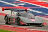
Another bit of drama.
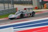
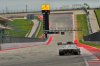
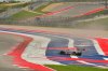
Saturday. Cold at 8am, 50f. Track very cold and covered with grit and dust. COTA ground the track nice and perfectly flat for the Moto GP the following weekend a few days before we got there. I never can understand how profession racers can't race on a perfectly fine track with even the slightest bumps. In any case they tried to clean the track but basically failed before we used the track for the first time on Saturday morning warmup session.
The grinding machine made nice little uniform pebbles about a 1/16" in diameter........billions of them! The back straight was so bad you couldn't see through the dust and particles as car ahead of you went into the cloud. Fuck! I have been in motocross races that were worse but not many!
Anyway, got off the track after a couple of laps. They went back out with the jet blowers and tried again and by the time I got back out on track in the first session two other groups had run and it was a hour latter so things were better, Not good but better. Fairly clean line but the off line was still bad.
So......setup changes. Still same shock settings and springs. added another 1/2 degree of camber, so now I have -1.5 F and -2 R. Added another degree of AOA to rear wing, now at +5. Tire pressure cold 28 all. I like that setting and the car seams to like it.
Had a hard time putting heat in the car, tires and brake, because of the procession nature of the track conditions, but all went well. Water temp still rock solid at programed temp 181F, oil temp at 210-120F, GRBX temp at 180-190F. Tires only pumped up 1-2 PSI.
2nd session, air temp up to about 65F, all setting same as 1st session, brakes began to warm up and tires gained 3psi. Car ran good. Carb better with reset floats about 1/16" above center of float window in Proform carb. That's just a bit high. Changed power valve from 4.5 to 7.0. I have been tuning carb and now have 12-13 "s of vac @ 1100Rpm idle.
Engine now better and runs clean down to about 1500rpms. Much less stumble off corners. If kept above 2500 runs pretty good. I can pull new ZO6 in straight line on back stretch. He asked me later in the day what I had in it and "old SBC with a carb" put a frown in his face.
3rd session, Gave wife ride............she did good lasted whole session. I ran at about 90% of my comfortable pace and she said she had fun. No data too slow.
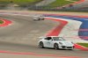
4th session, Ran it hard, Could almost stay with GT3 Porsche drive pretty well. We had a bit of fun together lapping traffic. Car was perfect on temps still, tires went up from 28 hot to 33 hot. Brakes are good but will want to try a better pad with higher friction value. Still on BP10 wilwoods.
Sunday, 1st session good fun like 4th on Saturday. I'm starting to think that it may be time to move up a run group. Really big speed difference at end of straights with some cars. Morning cool, track cleaner and line is quite a bit wider. I think they worked on it over night. All data like yesterday, temps still good, tires warm up and brakes good when heated.
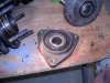
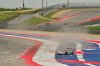
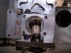
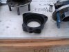
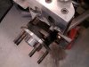
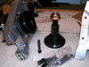
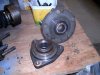
Drama session....................second lap spun hard between 15 and 16. Tank slapped twice and then went around a couple of times. Brake peddle on floor with little to no brakes. That was because the pads on the L rear were being knocked back by the upright/caliper waving around on the rotor/wheel. Got it stopped all good no other damage. Track guys were very careful and asked if I could steer it after report from corner worker said I had a suspension failure. Slow tow and back at trailer found problem.
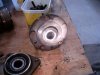
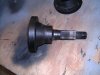
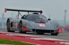
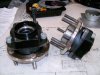
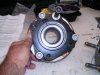
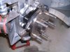
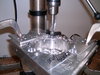
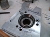
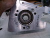
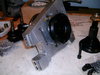
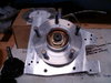
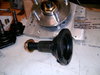
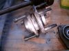
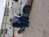
The post mortem. The broken one is the Drivers side. The complete one is the other side but if you look closely something is going on in between the bearing barrel and the wheel flange. Race coming out? The last one is me and the co piolet.
Saturday. Cold at 8am, 50f. Track very cold and covered with grit and dust. COTA ground the track nice and perfectly flat for the Moto GP the following weekend a few days before we got there. I never can understand how profession racers can't race on a perfectly fine track with even the slightest bumps. In any case they tried to clean the track but basically failed before we used the track for the first time on Saturday morning warmup session.
The grinding machine made nice little uniform pebbles about a 1/16" in diameter........billions of them! The back straight was so bad you couldn't see through the dust and particles as car ahead of you went into the cloud. Fuck! I have been in motocross races that were worse but not many!
Anyway, got off the track after a couple of laps. They went back out with the jet blowers and tried again and by the time I got back out on track in the first session two other groups had run and it was a hour latter so things were better, Not good but better. Fairly clean line but the off line was still bad.
So......setup changes. Still same shock settings and springs. added another 1/2 degree of camber, so now I have -1.5 F and -2 R. Added another degree of AOA to rear wing, now at +5. Tire pressure cold 28 all. I like that setting and the car seams to like it.
Had a hard time putting heat in the car, tires and brake, because of the procession nature of the track conditions, but all went well. Water temp still rock solid at programed temp 181F, oil temp at 210-120F, GRBX temp at 180-190F. Tires only pumped up 1-2 PSI.
2nd session, air temp up to about 65F, all setting same as 1st session, brakes began to warm up and tires gained 3psi. Car ran good. Carb better with reset floats about 1/16" above center of float window in Proform carb. That's just a bit high. Changed power valve from 4.5 to 7.0. I have been tuning carb and now have 12-13 "s of vac @ 1100Rpm idle.
Engine now better and runs clean down to about 1500rpms. Much less stumble off corners. If kept above 2500 runs pretty good. I can pull new ZO6 in straight line on back stretch. He asked me later in the day what I had in it and "old SBC with a carb" put a frown in his face.
3rd session, Gave wife ride............she did good lasted whole session. I ran at about 90% of my comfortable pace and she said she had fun. No data too slow.
4th session, Ran it hard, Could almost stay with GT3 Porsche drive pretty well. We had a bit of fun together lapping traffic. Car was perfect on temps still, tires went up from 28 hot to 33 hot. Brakes are good but will want to try a better pad with higher friction value. Still on BP10 wilwoods.
Sunday, 1st session good fun like 4th on Saturday. I'm starting to think that it may be time to move up a run group. Really big speed difference at end of straights with some cars. Morning cool, track cleaner and line is quite a bit wider. I think they worked on it over night. All data like yesterday, temps still good, tires warm up and brakes good when heated.
Drama session....................second lap spun hard between 15 and 16. Tank slapped twice and then went around a couple of times. Brake peddle on floor with little to no brakes. That was because the pads on the L rear were being knocked back by the upright/caliper waving around on the rotor/wheel. Got it stopped all good no other damage. Track guys were very careful and asked if I could steer it after report from corner worker said I had a suspension failure. Slow tow and back at trailer found problem.
The post mortem. The broken one is the Drivers side. The complete one is the other side but if you look closely something is going on in between the bearing barrel and the wheel flange. Race coming out? The last one is me and the co piolet.
Attachments


Last edited: