SLC 24 Howard Jones

Howard Jones

Supporter
Will: The back needed 1/8" spacers along with the steel collar on the dust boot to account for the taller Moog BJ. I am doing the front again with the new Moog BJ's this week. As I get things apart and measure them I'll let you know. Thanks for the heads up.

8e9bcb36fe8c42d53acf099bdfe68518_view.jpg
 
Last edited:

Howard Jones

Supporter
I have found a way to reset the rotors back in their original placement in relation to the calipers. Remember that the C7 bearing in about a 1/4 inch shorter than the C4 piece it replaces. This moves the stack height of the wheel stud face, rotor, and wheel inboard that same 1/4 inch but leaves the caliper mount on the upright that did not move. This causes the caliper to be out of alinement that same 1/4 inch.

I looked at and considered a few ways to accommodate the misfit, most of which resulted in a spacer in one place or another. First the C7 bearing cannot be simply moved outboard with a spacer. This will pull the stub shaft outboard with it and use up what little clearance is left between the stub shaft bell and the upright that is left.

Then putting a spacer between the rotor and the wheel flange uses up the height of the centering ring to index the wheel. And I don't like spacers to begin with so what's left? Move the rotor with the hat offset. After all that's what it's for, to set the position of the rotor in relation to the wheel/ upright.

So I decided to trim off some of the off set on the hat. After a lot of measuring that came out to .23 less offset. Then I had to find a machine shop locally that would do a small project like this. A few weeks later I had them done by New Braunfels Machine Inc. Thank you to Bryan Murphy and his guys.

Now to put it all back together with the new spherical bearing ball joints I ordered from Fran.
 

Attachments

  • HPIM2417.JPG
    HPIM2417.JPG
    517.4 KB · Views: 656
  • HPIM2418.JPG
    HPIM2418.JPG
    817.3 KB · Views: 673
I have contacted RCR about the availability of the spherical bearing retrofit piece and would be interested in at least having a look to see if I want to re fit them into my car. More on that if I get any info from RCR.

If anybody has pictures of these pieces please post them.

You mean these?
20161012_061016.jpg
20161011_114023.jpg
 

Howard Jones

Supporter
Yes I think those are the ones. I haven't seen them until now but those look just as described. I ordered them from Fran yesterday.
 

Howard Jones

Supporter
I got my spherical bearing retrofit kit from RCR. It looks like a very well made kit. More as I install it
 

Attachments

  • HPIM2420.JPG
    HPIM2420.JPG
    677.4 KB · Views: 591
  • HPIM2421.JPG
    HPIM2421.JPG
    796.3 KB · Views: 598
  • HPIM2422.JPG
    HPIM2422.JPG
    639 KB · Views: 527
  • HPIM2423.JPG
    HPIM2423.JPG
    690.3 KB · Views: 596

Howard Jones

Supporter
I started to put this all together today and I started with the fixed parts of the spherical bearing ball joint mod.
 

Attachments

  • HPIM2424.JPG
    HPIM2424.JPG
    804 KB · Views: 485
  • HPIM2425.JPG
    HPIM2425.JPG
    890.7 KB · Views: 440
  • HPIM2426.JPG
    HPIM2426.JPG
    847.5 KB · Views: 475

Neil

Supporter
Looking really good, Howard. I'd recommend bending the cut ends of your safety wire back on itself; Those ends are sharp and eventually you'll gouge yourself on the sharp ends.
 

Howard Jones

Supporter
OK I will, my safety wire technique isn't much above a c- but I have seamed to keep things from falling off over the years.

On another matter: if the usual torque spec for a 7/16 - 14 grade 8 is about 50 ft pounds. BUT if is threaded into a 6061 aluminum body does that alter the recommended spec. If it does is there a standard for this. I am concerned about pulling the threads out of aluminum so I have usually torqued to lower numbers in the range of bolt specs. In this case I used 45 ft/lbs for the cap screws into the uprights with blue thread locker. (242)

https://www.boltdepot.com/fastener-information/bolts/US-Recommended-Torque.aspx
 

Neil

Supporter
Howard,

If the hole depth is 2 x bolt diameter and the bolt is threaded all the way in, the 50 ft lbs is a safe value.
 

Howard Jones

Supporter
So far found this:

http://www.futek.com/boltcalc.aspx?mode=metric

With a grade 8 7/16-14 screw into 6061 T6 at 1 inch depth it comes up with:

recommended torque = 54 ft /lbs
Maximum torque = 77 ft/lbs

At 3/4 depth

recommended torque = 50 ft/lbs
Maximum torque = 67 ft/lbs

At 5/8 depth:

recommended = 44
Maximum= 58

So now we know.
 
Last edited:

Howard Jones

Supporter
It's funny how your fingers just seam to know. 45 just felt right and I can see that 50 is a good educated/experienced estimate.
 

Howard Jones

Supporter
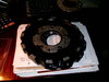
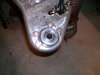
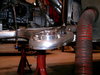
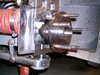
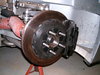
Well, well, well. After all that measuring and fiddling around with the stub shafts, wheel bearings, caliper mounts, etc. I measured up my driveshafts CV end to CV end and compared that to the gearbox output flange to stub shaft flange distance and WALL AH!!!!!. Exactly the same to within a 1/8 of a inch. 23 inches at normal ride height. This was one of my primary goals, to not need to replace the driveshafts and still change over to C7 type bearings. I did need to alter the caliper mounts and rotor position at the rear but that was pretty cheap to do.

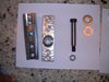
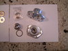
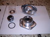
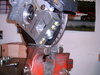
So that means that I don't need to change the driveshaft length and can reuse what I have. Friggin perfect! Merry Christmas to Me! Now back to the fronts and to install the spherical bearing retro fit kit.

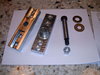
I will come up with a summery with part numbers and vendor information along with a total cost when I have the car completely back together. This has been quite a evolution to retrofit my original non race suspension to C7 type bearings but I think this is the right thing to do. At least for me.
 

Howard Jones

Supporter
I forgot to mention that I did use a 1/8" thick wheel spacer so that I could get a good wheel to caliper clearance. The close fit came from the rotor hat machine work. It would have cleared but by 20-30 thou. I think I'd like to have a bit more than that so I used some spacers I had in the leftover pieces box. Otherwise all fits up well.

Merry Christmas to you to Robert.
 

Howard Jones

Supporter
So I finished up the front of the car by installing the spherical bearing kit from RCR. Pretty much went together as designed. I like this much better than the ball joint arraignment. The whole thing was pretty stiff because of the stricture in the ball joints. Now the entire front is nice and smooth. The bottom arm moves around just like the top does. Much better in my opinion. I really don't think there is much less effective XYZ travel either.
Here's some pictures of the front complete setup with spherical bearings or rod ends at all positions and C6-7 hub assembles. This is as near I can make it to the race suspension starting with the original street suspension parts.

The rear corners are C7 hubs with top of the line much beefier stub shafts to suit. This is a strong as I can make it with again keeping the original uprights and a arms.

So how much for the whole deal, all four corners?

Spherical Bearing kit (all 4 corners) 1000.00
Front hub adapter kit (pair) 482.99
Front C6 bearings (pair) 559.00
Rear Stub Shafts (pair) 633.98
Rear C7 bearings (pair) 297.00
Drilled Head hard wear 32.76
Machine work 50.00
Machine tools 34.00

Total 3089.73
 

Attachments

  • HPIM2427.JPG
    HPIM2427.JPG
    794.4 KB · Views: 445
  • HPIM2428.JPG
    HPIM2428.JPG
    827.1 KB · Views: 438
  • HPIM2430.JPG
    HPIM2430.JPG
    915 KB · Views: 449
  • HPIM2432.JPG
    HPIM2432.JPG
    777.2 KB · Views: 417
  • HPIM2433.JPG
    HPIM2433.JPG
    871.9 KB · Views: 490
  • HPIM2434.JPG
    HPIM2434.JPG
    905.7 KB · Views: 518

Ken Roberts

Supporter
I have a question for you Howard. Both Paul and I had to increase our axle lengths by 1 inch to use the new C7 hubs and C7 stubshafts. I know you are about a 1/4" inboard of what we were with the new C7 hubs due to you just bolting the new hub up to the flat slab on your Gen1 uprights so I would assume you would need new axles made that are 3/4" longer. I guess I could have pulled my cv joints as far apart as they would go on the shaft and mine might have fit too but then the steel balls and cage internally would not be approximately centered in the CV joint body. Your thoughts on this?
 

Howard Jones

Supporter
Frankly I am a bit surprised also. I think there is enough difference in the uprights that in effect allow the bearing to seat in it farther inboard on the old upright than the new types. I was a bit shocked when I first made my measurements and saw that the old driveshaft length laying on the bench was exactly the same length as the flange to flange measurement I had just made of the stub shaft to gearbox flange measurement. I must have looked at that a dozen times before I just placed the drive shaft in the car and it fit dead on. I am certain that the CV joints are sitting at their "free" or unloaded positions when measured. It's not that I made it work by using up all the plunge. Of course the car is sitting on its tires at normal ride height. The stub shaft big nut is torqued to 180 ft/lbs.

I did however continue to locate the bearing as far inboard as possible as I worked this through. I knew that I could redo the rotor/caliper location if I need to, as I did. In addition I would note that I never removed the lower A Arm's from the car or altered their adjustments. I also have completely different pieces. Porsche G50 and different uprights. There's no accounting for dumb luck.
 

Howard Jones

Supporter
I am at a lull in things I have planned for changes on my SLC. So I was looking for something to do and I found a couple of pints of fiber glass resin that still was good. I was impressed with what Cam did with his radiator ducting and so I added a exit snout. Same old method, carboard, duct tape and a some hot glue for a one time mold.

I really think that this type of ducting is necessary. I also think it adds a significant amount of downforce in that all that air going into the front of the car if forced out over the top and none gets underneath. By the way, it also serves to keep heat from the radiator off the front of the footbox and it works very well in that regard.

Pictures are previous and newly completed.
 

Attachments

  • HPIM1653.JPG
    HPIM1653.JPG
    144.6 KB · Views: 380
  • HPIM2435.JPG
    HPIM2435.JPG
    910.5 KB · Views: 453
  • HPIM2436.JPG
    HPIM2436.JPG
    780.9 KB · Views: 475
Back
Top