So I think I know what happened, at least without a follow up drive to see if the vibration has gone away. That isn't that easy to do as this isn't a street car and I need a few 70mph stops to really see if it is rotor heat related.
I took all the rotors and calipers off the car and inspected them. The rotors had no real runout error as well as the hats. The calipers seamed to be ok. All the pistons feel about the same when compressed individually by hand. The fluid looked fine, not black and overheated. Wheel bearings, spherical bearing. and all suspension rod ends all check ok. Nothing cracked (chassis, suspension parts, etc.
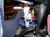
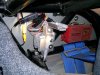
So on to the half shafts. The drivers side was attached as normal, when I took it off I tried to check torque settings and as best as I can determine all screws were still at near 57 ft/lbs. The passenger side had all hardware in place on the inboard side and still in the CV on the upright end but unattached with two broken screws, and one bent. The stubs hafts were undamaged. I chased the threads but they were fine. The big ass nut was still at near 200 ft/lbs on both sides.
All four CV's seamed to be fine. (I just love to clean and inspect CV's) Four beers and all afternoon right there! I did find that the screws supplied by RCR with the car were 55mm long and the screws supplied by Drive SS were 60mm. The 60mm screws protrude through the flanges about 2mm but do not interfere with anything. No real difference there but I installed the longer DSS length 60mm drilled head screws I bought elsewhere so I could safety wire them. ( that is another couple of hours).
So what happened? My best estimation is that I had torqued all four CV's to the first torque stage, 35 ft/lbs, and when I moved on to the final setting of 57 ft/lbs I missed the passenger side outer CV. That left it at 35 ft/lbs. That WILL NOT hold it together. Thus the vibration.
I should add in hindsight, there was no brake peddle modulation that is normal with a warped rotor. That should have been the important data point in my troubleshooting methodology...…………….
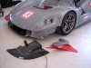
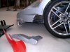
At the track I was looking for a brake problem and did not find anything. I did tighten two caliper cross bolts but that wasn't it. I taped off the air inlets to see if the rotors were indeed being cooled differently side to side and that's when I had the problem. Separately this is a real design concern however so I have used some sheet metal to block off airflow to the face of the rotors and direct all the cooling airflow into the center of the rotors.
Conclusion: When you are at the track alone and it is hot as the ass of the devil in the paddock it is very hard to work on your car alone, troubleshoot issues, do all the jacking and taking apart tires etc, and then do your own quality control, all with time constraints. Ya I know "well what's the problem yata, yata, yata." It IS a problem and I have learned it a couple of times over the years. You just want to figure it out and get back on the track, partly because it's really the only real chance you have to test. The hurry up is what gets you. It really is the reduction in the time you have to think, not really to do the work, so you end up doing what you have time for instead of working through a logical train of thought. But then maybe it's just me.
If the car (bike) feels wrong, that's because it is wrong. TAKE IT HOME AND FIX IT!!!!! where you have all your tools and plenty of time to do it right. The above cleanup, inspection and re installation I went through took all of 4 days @ 4-6 hours a day.
Oh, I have a work log book now and I have everything like CV screws torque sequence in writing, checked off as completed. As well as many other things like big ass stub shaft bolt, caliper mounts, rod end jam nuts, suspension inspection per corner and some other things.
I have written all of this stuff in my build log (sort of a public shower on the front lawn) so that others can see what it has been like for me to build, develop, test, repeat, repeat, repeat. I hope it serves some positive purpose for other armature home builders like me.
Oh, and thanks Neil. That was a pretty good article and good information on the early days of vented rotors. As I started reading on rotors design I found out that the iron material Ford settled on has become the industry standard used by everybody now including Wilwood. In my reading I found several references to venting from the inside as the appropriate way to cool a rotor. Good stuff thanks.
Randy, my hats are torqued in sequence and safety wired as per the Wilwood instructions and best practice. Thanks.