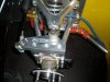
Got a care package from RCR with my masters. They built up well. Had to cut oof about an inch of the master rods because i put the masters inside the car. I've got to figure out how to mount that standard LS Drive by wire to the RCR gas pedal. BTW, the 5/16 jam nuts are fine thread. the master cyliner fasteners are 8mm.

- Forums
- GT40 Replica Manufacturers' Corner
- RCR Forum - RCR40/SLC/917/Superlite Aero
- The SLC Clubhouse
You are using an out of date browser. It may not display this or other websites correctly.
You should upgrade or use an alternative browser.
You should upgrade or use an alternative browser.
SLC 36 Cam's Build
- Thread starter Cam MacIsaac
- Start date
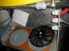
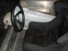
Got a care package from RCR with my masters. They built up well. Had to cut oof about an inch of the master rods because i put the masters inside the car. I've got to figure out how to mount that standard LS Drive by wire to the RCR gas pedal. BTW, the 5/16 jam nuts are fine thread. the master cyliner fasteners are 8mm.
Does the gas pedal have a provision for an old-fashioned cable gas-pedal-setup?
Cam,
I believe venting to the outside is far safer than venting into the engine compartment (sparks and gas vapors don't mix).
I'm studying the vent and found myself thinking - if you take a really hard corner, and your tank is really full, if you vent it outside won't fuel come surging through the hose and puke everywhere?
Perhaps this is a silly idea (although i could have sworn I saw it somewhere before), but couldn't you weld a -8an (or similar) bung somewhere into the filler neck setup at the top (by the gas ap), then run the vent hose from the vent to the weld-in bung. (so basically it vents into the filler hose, near the top).
Good idea? bad idea? really bad idea?
Basically the same as you would try to pull yourself out of the water on your own hair.
Venting is basically not for exhausting fume it is moreover for avoiding a vacuum in your tank to allow fuel still beeing sucked out by your pump.
Your idea would work if you would have a vented cas cap ( but than you wouldn´t need any vent line either).
So if your cas cap is not a vented one you need an external air supply to the tank.
Best way to do it is with a vent valve.
Aero Tec Laboratories, Ltd. Racing Fuel Cells - PRODUCTS - Vent Valves
INLINE BREATHER/VENT VALVE 5/16 PUSH ON
and than run the hose outside. There shouldn´t be any spill or surge .
TOM
Okay - thanks for the heads up.
With the ATL one, if you were going -6 vent line hose, which would you recommend using?
I don't really understand the difference between
-6 inline vent valve rollover only
-6 inline vent valve ss rollover nylon float
-6 vent valve roller float 200mbar
Ideally I'd like to run a hose from my vent fitting in my tank, to probably the middle of the car where the inline vent valve is, then direct my hose somewhere infront of the car)
I like the Merlin one, but since my vent is -6an, I want to just use braided -6 all the way
edit: Although I suppose thinking about it, I'm not certain why I'd want to put it inline half-way down the car. Just attach it to the tank's -6 vent fitting, then run my hose where I want it to go....
Last edited:
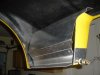
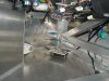
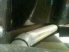
Got the holes cut into the FG for the outbound and inbound coolant lines. also took the vent line through. I put the photo of frans mule on there too. he did take out the entire bottom of the FG body. Decided to only take out arc for the lines and leave the rest. i can alway take it out later and it is firmly in place. i think you could hang a side of beef on these lines!
I know i took the easy route and didn't weld up Al lines. I used .065 Al 1.5" tubing 90% of the way til the ells.. The Silicone elbows are only exposed for an inch or two. Unless they take a hit from a large chunk of material thrown up at just the right angle, i should be ok. If that happens, i'll be visiting the welder !
I know i took the easy route and didn't weld up Al lines. I used .065 Al 1.5" tubing 90% of the way til the ells.. The Silicone elbows are only exposed for an inch or two. Unless they take a hit from a large chunk of material thrown up at just the right angle, i should be ok. If that happens, i'll be visiting the welder !
Attachments
Got the expansion tank mounted. I'll have to have my kids with small hands get the radiator cap on!
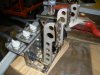
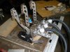
Also picked up some 3" LS7 exhaust manifolds. i may have made myself a fabrication nightmare the way they exit straight down. but going from 2.5" to 3" was too tempting. The vette forums had 20 posts where LS3's went up 20-30 hp. Anyone see any problems? I've been told these manifolds are made of Aluminized Steel? Any problems welding 304 SS to them?
Also picked up some 3" LS7 exhaust manifolds. i may have made myself a fabrication nightmare the way they exit straight down. but going from 2.5" to 3" was too tempting. The vette forums had 20 posts where LS3's went up 20-30 hp. Anyone see any problems? I've been told these manifolds are made of Aluminized Steel? Any problems welding 304 SS to them?
Attachments
Cam, I think they are hydroformed stainless steel (not sure of grade). A Hastelloy "W" TIG filler rod will work very well for this. I intend to use the same manifolds on my engine as they flow as good as any aftermarket header and better than some up to slightly above 7000RPM. IMO, of course. Keep an eye for wreckers parting out
the center exhaust sections for the LS7. They have the mating flange and most turn 90 degrees. They should heve good clearance in the SL-C.
the center exhaust sections for the LS7. They have the mating flange and most turn 90 degrees. They should heve good clearance in the SL-C.
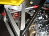
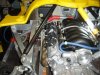
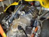
Just got a pm asking about the lines:
3 blue lines in the pic.
One pcv return from block to intake manifold.
One is vent coming from drivers side radiator. I got it right woohoo!
One is steam line coming off block that will be t-ed into the top of Moroso with the radiator vent.
See any problems?
3 blue lines in the pic.
One pcv return from block to intake manifold.
One is vent coming from drivers side radiator. I got it right woohoo!
One is steam line coming off block that will be t-ed into the top of Moroso with the radiator vent.
See any problems?
1 - In the first picture, what's the blue tube above the coolant line? Wiring harness?
2 - After much (probably wasted) time researching, and thinking, and researching, and fretting, over the vent valve (and thinking about explosions due to fuel and fumes, hahaha) I ended up with a fuel safe discriminator valve
discriminator valve, -8
Basically its magic ball bearings inside determine if fuel or air is trying to leave. If air, yes, if fuel, no. Nice and simple.
Efn, that's the vent off the drivers side radiator bleed. i haven't cut the lines to fit yet, so leaving some excess.
Also, Gotta figure out the expansion tank drain. thinking of returning it to the heating line return. Then i don't have to cross the belts and the front dress of the engine. Right now i'm looping the heater outbound directly back into inbound. i may put heat on it later but we don't have any -30 weather here! Does anyone know why i couldn't return the expansion tank to the heater hose return?
Also, Gotta figure out the expansion tank drain. thinking of returning it to the heating line return. Then i don't have to cross the belts and the front dress of the engine. Right now i'm looping the heater outbound directly back into inbound. i may put heat on it later but we don't have any -30 weather here! Does anyone know why i couldn't return the expansion tank to the heater hose return?