
- Forums
- GT40 Replica Manufacturers' Corner
- RCR Forum - RCR40/SLC/917/Superlite Aero
- The SLC Clubhouse
You are using an out of date browser. It may not display this or other websites correctly.
You should upgrade or use an alternative browser.
You should upgrade or use an alternative browser.
Howard Jones
Supporter
Jac, some of that may have come from the flat tow back to the paddock, positioning the car to winch it into the trailer, unloading it at home and driving it into my shop. I any case I had no warning before the car just took off. The fatigue crack held up until it saw that last big load then it just continued through the joint section until it came apart..........very quickly.
Like I have said previously the C4 bearing was never designed for this and in hind sight it was just a mater of time. I had been watching the wheel bearing for increased play and had not detected any at the rear. If asked before hand I would have expected to see some increased play in the bearing before failure. But then you never know what you don't know.
Like I have said previously the C4 bearing was never designed for this and in hind sight it was just a mater of time. I had been watching the wheel bearing for increased play and had not detected any at the rear. If asked before hand I would have expected to see some increased play in the bearing before failure. But then you never know what you don't know.
Last edited:
Ken Roberts
Supporter
Could very well have been substandard off shore bearings originally supplied with the car. Perhaps buying/using Timken or SKF for a season might be the cheapest road to take.
Howard Jones
Supporter
I think that would be a unfair statement. I was the first guy to call Fran and ask if he could work with me to build a SLC track only car. It was being sold as a street car at the time and before he built his race car. This was something like 2006-07. I took delivery about 6 months later. Nobody had any data on these car then and as far as the C4 corvettes go not much on them either.
Lets face it.... you can't expect Rolex series prototypes for used corvette prices. As far as who the vendor was for those bearings....well it just doesn't matter now does it, they were made more than a decade ago. I'll pull my big boy panties up and take complete responsibility for the construction of my car. Period.
I pushed the car much harder at COTA because of the huge runoffs and the safety they afford testing a new car. I picked my spot and the car broke. If people think they can build these cars and take them to the track, push them many multiples harder than even possible than on the street, and not break them then I think they are fooling themselves.
I broke parts on bikes and got hurt.......real hurt. I don't do that anymore....but that doesn't mean I'll retire to the couch just yet either.
I don't think C4 bearings are suitable for high power cars on slicks being run hard on race tracks no matter who makes them. ALL the corvette guys seam to know that. We (many very knowledgeable people have contacted me on the subject) will come up with a much stronger package, add a time change program if necessary to that, and post everything I learn from doing so. This is one of the reasons why I have built and am developing this car in public.....to lend a bit of reality to the bench racing.
So there is no blame here.....just truthful information.
Ed, the stub shaft splines go in the back of the bearing housing, all the way through the bearing and out the other side. It's the lack of material thickness in the bearing shoulder itself that is the problem. This is completely evident if you compare the C4 design to the C5-6-7- X Tracker design. The answer is to retrofit to the X Tracker design. It is becoming evident this is the solution on both the front and the back of the car. This is the direction I am heading and as hard parts become available..............watch this space.
Last edited:
I used the C4 hubs on the rear of the BT24 Replica as well and found the same problem, initially thought it was because of the 15" wide wheel with only a 6" back space, but ive tried cheap ebay units to top Timken and they all last the same, not very long approx 100 track miles and there shot. so the present owner has just resigned to replacing them regularly as soon as any play develops.
cheers John
cheers John
HCF - John
Gearbox / Brake Systems
I spent some time speaking to SKF's USA motorsport head this morning. He believes the X-Tracker would be a good candidate for this project and I've arranged to source them direct if we wind up moving forward.
As was discussed earlier in this thread, there are several options within this line we can use - with both spline count and ABS sensors being the main differentiators.
C5 - 30 spline count, passive abs system (bob & magnet) - delphi sourced
C6 (05-08) - 30 spline count, passive system (same as C5)
C6 (08+) - 33 spline with active abs (hall effect sensor - power to sensor) - bosch sourced
C7 - 33 spline, active
Any of these will work fine for our purposes - is there a preference from anyone planning to use traction control and can adapt sensor for that purpose?
Best,
John
Ken Roberts
Supporter
The C7 rear X Tracker hubs (BR931001) are less than half the price of the C5/C6 X tracker hubs. Most owners would probably just use the axle mounted add on reluctor wheels anyways.
SKF Bearings Wheel Bearing and Hub Assemblies BR931001 - Free Shipping on Orders Over $99 at Summit Racing
They are even cheaper at Rock Auto. The custom suspension hot rod crowd are scooping them up.
SKF Bearings Wheel Bearing and Hub Assemblies BR931001 - Free Shipping on Orders Over $99 at Summit Racing
They are even cheaper at Rock Auto. The custom suspension hot rod crowd are scooping them up.
Last edited:
Ken Roberts
Supporter
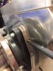
On our second Gen rear uprights (like mine shown in this picture) it's too bad we couldn't just machine the stock protruding flange flat and get a special billet adapter created to take up the difference in depth and bolt pattern of the C7 hub. . My Pen is pointing to the protruding flange that could be machined off. You could supply us with a special adapter and new design 33 spline axle stub shaft. We could then take our uprights to a local machine shop to have the existing protrusion removed.
Attachments
Ken Roberts
Supporter
I just measured that flange I was pointing to with the pen in the previous post. It is about .310". The difference in thickness between the C4 rear hub and the C6 X Tracker hub is also about .310". So the billet adapter would be about .620" thick.
You may get more SLC and GT-R builders interested in this upgrade if it was more like $1500 for adapters and stub shafts instead of $3000 for new uprights and stub shafts.
You may get more SLC and GT-R builders interested in this upgrade if it was more like $1500 for adapters and stub shafts instead of $3000 for new uprights and stub shafts.
Last edited:
Howard Jones
Supporter
Ken, Those of us that are working on this are aware that the 2nd gen upright is different than the one on my car's 1st gen. type with it's completely flat upright face. The 1st gen is really quite straight forward to fix. Just a flat steel plate with the center hole and 6 holes in it really. But the 2nd gen is where the quantity potential is and it has the added feature of a double shear toe link mounting system.
Ken Roberts
Supporter
Your 1st gen upright adapter plate will not be as easy as you think to make. Your plate can only be about .310" thick. How are you going to captivate the three bolt heads in the plate when the plate has to mount flush to the upright. These are the bolts that protrude through the adapter plate to fasten to the C7 hub. Just a thought. You will need to drill three pockets in the upright face to accommodate the protruding bolt heads.
I hope I'm not irritating you Howard. I'm just letting other owners in on some of tech involved in this type of upgrade. I'm sure there are tons of people following this thread you created.
I hope I'm not irritating you Howard. I'm just letting other owners in on some of tech involved in this type of upgrade. I'm sure there are tons of people following this thread you created.
Last edited:
Howard Jones
Supporter
Ken, you have been a big help. Thank
The hub uses a 12mm bolt. The hole for them go all the way through the upright. The counter sink depth on a 12mm flat head allen bolt is right at .25" and we have .31" to work with so I think we are ok on thickness. The radial direction may be close but if we have to we can press a 1/2 inch .095 wall tube in the 12mm hole drilled out to .5 in the upright and re-drill to 5/16 id. Then use a 5/16 flat allen head bolt to clamp the adapter in place.
Remember in addition the adapter will have 3 12mm bolts all the way through it and the upright to hold on the bearing assembly.
This would be for the gen. 1 upright. A better look at the gen. 2 upright would be necessary to work out a solution for it.
This all doable with very simple mill work. Others with much more knowledge than I are also working on this so we will see what comes from that.
Attachments
Last edited:
Ken Roberts
Supporter
Those aren't designed to be used in critical high strength applications. Absolutely no way would I use them. I worked with fasteners for a living.
HCF - John
Gearbox / Brake Systems
You may get more SLC and GT-R builders interested in this upgrade if it was more like $1500 for adapters and stub shafts instead of $3000 for new uprights and stub shafts.
Ken,
Funny you should mention that - SKF Motorsports Head and I spoke about adapters this morning. He was familiar with the one's already being made to retrofit the X-Tracker's.... he felt it was a poor solution for this type of thing.
I don't know how good they are, but I believe there are existing sources for stub axles for about $1k, and adapters/bearings for the front are est $1200. If you assume the same $1200 cost for adapters/bearings for the rear, which might not hold true, you're in the $3400 ballpark for the sub-optimal solution.
Best,
John
Howard Jones
Supporter
Ken how about three 1/2 dowels to locate the adapter plate. They could be embedded aprox 1 inch into upright and again 5/16 into the adapter. All very close tolerance. If any movement of the assembly is observed then new uprights would need to be substituted.
Ken Roberts
Supporter
Dowels won't help much with a pulling force on the plate. Don't get me wrong in that they are a good idea. A dowel would mainly help with the rotational force on the plate.
I'm sure Cam T could offer some advice as I believe he's a Mechanical Engineer.
I'm sure Cam T could offer some advice as I believe he's a Mechanical Engineer.
Last edited:
Ken Roberts
Supporter
I would make the plate out of chromoly and then use socket head ARP fasteners. The socket heads could line up with three holes drilled in the upright offset from the three current holes.
Although the use of adapters with X Tracker hubs like on my front SLC uprights would be frowned upon in a serious level of racing I have never heard of one failure yet from use in the front of the much heavier Camaros who extensively race with them in place. They have been hard on them now for three seasons.
In the end if a new upright isn't that much more .....than a adapter may not make sense.
Howard are the forces applied to the front hubs higher than at the rear?
Last edited:
Howard Jones
Supporter
Ken, I am suggesting using dowels to rigidly locate the adapter plate in place so that the hub is firmly located on the upright by its center indexing shoulder. Then the clamping force is provided by the three other hub mounting bolts that go all the way through the upright, adapter plate, and then fasten to the hub itself.
I don't propose bolting the hub to the adapter and then the adapter and hub as a sub assembly to the upright. This is possible due to the uniform outboard surface of the upright on the gen 1 version.
Or............... weld a 5/16 aluminum (6061) plate onto the outboard face of the upright and re-drill for the new hub.
Or............... make a new gen 1 upright that is 5/16 thicker and live with the additional weight. This is more than likely the strongest option.
What do you think Cam ?
Last edited:
Ken Roberts
Supporter
That's interesting. So the adapter becomes a spacer. That's fantastic as long as the inboard side of the upright has flat areas to accommodate the 3 bolt heads.
Can you post a picture of the backside of your Gen1 upright.
I would skip the C6 X Tracker hub and go right to a C7 hub instead due to how much cheaper they are as long as you can get a 33 spline stub shaft to fit and play nice with your existing axles.
Can you post a picture of the backside of your Gen1 upright.
I would skip the C6 X Tracker hub and go right to a C7 hub instead due to how much cheaper they are as long as you can get a 33 spline stub shaft to fit and play nice with your existing axles.
Last edited:
Similar threads
- Replies
- 12
- Views
- 1K
- Replies
- 15
- Views
- 2K
- Replies
- 11
- Views
- 3K