Southern GT Chassis #54 Build - The What Have I Done Chronicles!!

Yes, that's the one. I'm not sure what range of motion your throttle plate makes, but its less then 90deg. So a 100deg measurement range is good enough, allows you for a bit of a range of motion with high precision of voltage output.
Can you share a picture of the TPS mounting without the TPS installed? We need to be sure that Jenvey hasn't gotten a unique D-shaft orientation when throttles are closed. They can do that, and would mean you'd need a custom programmed TPS sensor. (Or buy directly at Jenvey)
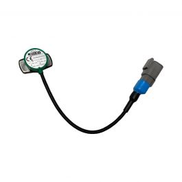
 

Shaun

Supporter
Hi, yes will send photo, VariOhm did get back with this

Not really, the Euro XPD offers up to 360deg with dual channel output which can be programmed in 10deg steps, different channel outputs along with offset electrical zero. .
Through hole vs blind hole.
Slightly different size although they both take a 8mm D shaft.

then I asked for a replacement for the TP11 in their frange and they said this

There is no direct replacement. The XPD would be the closest but you would need it programmed to the nearest electrical angle. Programmed sensors carry a 10pcs MOQ or you can use the standard 360 degree version which you can purchase in single units.

I will sort a photo really appreciated
Shaun
 
Thanks Shaun. Everything variohm says is true. However: there are choices to make. A standard range of 100deg (which is the cheapest) works best, and gives you the best TPS signal-to-noise ratio. I just bought one (1pcs MOQ) from Variohm of that spec myself, no custom programming.

To illustrate: If you use 360deg, that will work, but the 360deg signal is divided over 5V of measurement range electrically. So a +-0.01V fluctuation = 0.72% TPS position opening fluctuation. That's significant. If you however, use a 100deg TPS, that 0.01V noise in your signal is only 0.2% TPS position.
The people I was in contact with can do a custom program on a single one too, no MOQ on that. There is a 75euro fee for programming though. I've pasted my contact in germany below.

If the 8mm D shaft is the same, but now you need a blind hole, you just cut it of. (what I did)
The offset zero is indeed the most difficult one to solve. for that you need to know where your 'D' indent lies w.r.t to the sensor placement. To address this you can do 3 things
- Buy a sensor with a wider range
- Rotate the sensor/mounting holes to align electric center
- If your ITB throttle set shaft is a M7 thread (as it was on my webers), you can replace your nut with M7 billet 8mm bar which you file your own 'D' into. Check my 'Weber hack to EFI' thread on gt40s.


Heiko Wagner
Senior Sales Engineer (Position sensors) | +49 6221 3920 121
Standort Heidelberg | Hans-Bunte-Straße 10 | 69123 Heidelberg
Variohm Eurosensor Ltd | Towcester, UK | NN12 6HP
+44(0)1327 351004 | www.variohm.de | [email protected]
 

Shaun

Supporter
Just had another update from them

The sensor would give output over the full 360deg, even if you trim the electrical angle on the ECU.
 
From a sensor point of view yes, but on the ECU side no. The voltage output of the sensor being received by the ECU is senstitive to noise or ripples in the 5V line. I'm just saying that if you have a tighter TPS voltage output, your ECU will see a more stable and tighter TPS position. On the sensor the output accuracy is still the same, irrespective of how you program it, that's true.
 

Shaun

Supporter
The one they supplied with the manifold kit and Throttle bodies was the TP11 one and judging by the quality of the one I have its a clone of the VariOhm one probably made for pence but they shop out at about £70!!
 

Shaun

Supporter
Morning all in the grip of the Beast From The East!!!

Been far too long since and update but a major milestone as per the attached, had to link to one of our web servers as we cannot upload videos here but with the help of Geoff and chums at Taylor Automotive this was the result

Start Up

Not helped in any short means by the following

A broken TPS brand new from Jenvey, Chinese tat (did work if you angled the screwdriver on the wiper slightly) but they did replace FOC (as they should)

A duff MAP sensor so that was swapped for another brand, mine was a GM clone, tat again.

ECU was not set for dual LAMBDA but that was a config change.

Dual trigger dizzy took some setting up but is sweet now.

Minor fuel leak on the fuel rail, caught the O ring when fitting the pipe not a great HP fitting that's for sure, anyone any thoughts on that?

A MAP for a 351 not a 302 so not quite correct firing order!! Easy fix.


So she runs, bit lumpy but runs, plenty of water leaks but most sorted now, alternator I had in a different forum that is not charging just need bridging resistor to take the light out.

Oil pressure is showing about 60psi but I guess its a new engine so will be tight, I am not running it much yet more for testing alternator charge and leaks, etc.

So now onto body...Aaaarrrrgggghhhhhh...Actually have done some dry fitting and the fit looks not bad to start with.

Toodle pip all and stay safe.
 

Shaun

Supporter
So top tip of the night, when you remove the alternator loom just remember to kill the battery supply, which I did not so turned round a short while later to see a plume of smoke from the engine.....
Wire had dropped and clipped a nut and shorted, result one fried section luckily not so bad only bad to the main loom where it looped back to the starter, so a 15 minute job is now a couple of hours to sort, oh happy days!!! Just goes to show though how unfused cabling can cause a serious fire!!
 

Shaun

Supporter
Been too long since an update, where is the time going these days? Has Covid changed the spin of the earth, April whizzing by before we know it it will be the longest day. Not so much progress, finally finished a pool hut I started in the first lockdown, only took a year!!! Busmans holiday i guess....
Anyhow on to body fit now, had a trip down to see Mick & Carol and the gang to get some tips, decided though to get the gear linkahge working as was having trouble getting the gears which Mick said I should when dry.
So some adjusting tonight and I have them all now, 1st is the hardest to shift into the rest seem pretty ok.
One thing I have a fair bit of play on the gear rod on the apposite side to the linkage, in effect as below although my rod is a lot shorter on that side

1618866160027.png

Is that normal?
So just doing the gear linkage cover plates then will start back on the body, that from what I have heard is a challenge!! I will endeavour to update more often
Cheers
 
Hi Shaun,
"Is that normal?" - No!
I'd take the cover off & strip it to find out what's going on. I ended up making a new shaft for mine, as the selector was on the wrong side, so it can be resolved
Andy
 

Shaun

Supporter
Cheers Andy, mine was fully rebuilt by Chris Cole but the oil seals were forgotten just hoping nothing is forgotten here as well will drain and take a look, cheers
 
Hi Shaun,
I've just checked on a UN-1 that has just come back from Chris Cole for a refresh and there's zero play in the cross shaft. Looks like you may have to get the housing bushed or a larger shaft machined up
Regards,
Andy
 

Shaun

Supporter
Cheers Andy just heard back from Chris and yes its not correct so have to drain the box and send back to Chris to take a look, at least the whole box does not have to come out like last tine when the oil seals were missing. Thanks for checking yours really appreciated.
 

Shaun

Supporter
Body body body....So took the plunge and started on the body fit, so far and early days its not too bad, the rear clam is not a million miles away, some grinding round the top lip and had to oval the holes in the spider just to pull them out a little to fit the profiles as below

1619643040023.png


Alternate use for engine hoist but works quite well including butchers string to stop it swinging and a box to hold the rear at the right height or there about

1619643131448.png


Near Side

1619643156101.png


Screen then popped into place, it fits well in the opening, they is a little rocking on each lower corner but it takes very little pressure to sit it flat, I dont think it will stress the glass the sealnt should allowfor it to fit well

1619643248880.png


Front clam sits ok but really just dropped here for now, one question, is there a natural curve of the front clam centre centre aginast the spider section in the middle? Both ends sit well but the centre is low however the profile looks like it was meant to be like that.

Again earyl days but my off side cill looks quite short

1619643366729.png


And nearside even worse!!

1619643400699.png


I think Mick said sometimes you have to chop them down and also insert a bit, does anyone have the measurement from the clam to the cill? In effect the wheel arch diameter?

Also going to fit this chap, I really did not liek the linkage that came with my Jennvey kit as saw Simon had a really nice on so thats a respote form body work when it gets too much!!

1619643536241.png


Back on it tomorrow!!
 
Looking good Shaun, the Dzus mounts set the center of the front clip to the correct height, that is currently too low but will come up when you fit them.
 

Shaun

Supporter
Paul a damned good point!!!! There I was pondering last night not being able to sleep and I did wonder if there was another clip to hold that down like the rear
How about your cills did you have to chop and add or remove?
 
Back
Top