Tire compounds and safe suspension loads

To be sure I stay within safe limits I’m trying to figure how much my rear suspension loads would be increased from 1969 figures if I make some changes in tires and brakes. I’m sure improved compounds have increased the lateral G forces imposed in cornering and for straight line acceleration and braking, but I can’t find any consensus. It looks like modern aerodynamics have hugely increased down force and it’s hard to separate that from the tire compound’s.
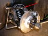
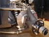
My suspension is almost identical to the F5000 Lola T140 (lower reversed a arm, single upper link, twin trailing arms), the tire size (13X10, 13X7.5) and HP (275-300) are about the same as well, but it’s 250lbs. heavier than the Lola’s 1280. If that car were equipped with modern brakes and tires, what kind of handling improvement (and suspension loads) would be likely to result?
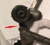
A related question is which rear suspension component is the most common one to fail catastrophically? I would think mounting points and journals, but I’ve got no racing experience to go by at all.
I don’t own a 40, but my Lotus is the same vintage and I hope this is relevant to this forum—If not, Mods, please move it to the correct one.
Thanks,
John
 
I generally back engineer on a none quantity.
Like if its running 5/16 rose joints and its lighter I run with 1/2" that sort of thing.
My lower rear arm I went to 2 lower laterals ,this gave 2 inner r/joints instead of 1.
Most things will bend in the testing period before they break.

Thinking about it it would come down to G's then you can calculate from their if you are into math.
So either way you will have to put your arse in the seat to get some numbers.

Or live on the edge John and suck it and see.

Jim
 
i remember reading an Allen Stainforth book some years ago (which i loaned to a freind an never saw again) in which, iirc, says something on the lines of the rear toe links contedning with a lot of force. That might be the area of the suspension to keep an eye on. But, I would just keep an eye on the suspension alignment as a whole. If your alignment is changing, somthing is most likely bending! We found this out first hand in our Formula SAE car back when i was in school.

What exactly is this car you have? Is it a downforce car? Do you have an idea what the Factor of safty the car was designed to have?
 
Jim-I'm still learning suspension statics and dynamics, and in this case, since I'm not a trained driver, it's better to concentrate on the engineering instead of just doubling a part's strength and giving it a try, no disrespect intended. It's one thing to risk my own ass (such as it is) on a hunch, but not someone else's.

John- I've gone over most of the rear components and found two trouble points. The shock absorber mounting bracket on the inverted rear a-arm had developed a 3/4" long crack running half-way down the flange slightly in front of the journal. I can't tell if that resulted from a flexing of the a-arm or a torque load on the journal. The other is a dent on the side of an upper lateral link opposite the spring. If that was a result of it colliding with the spring, that might be the cause of the split bracket, which seems more likely than a fatigue crack and wouldn’t require a stronger part. If I can’t tell visually, I’ll take the piece down the road to NASA and see if a friend there can pull a few strings with the materials testing guys. It helps that half the engineers working there are either NASCAR fans or hot rodders themselves!​
The car is an ex-works Lotus 47. It was used as a foundation for a high-powered road car, and the Lotus twin cam and Hewland FT 200 were replaced with a Ford 289/ZF 5DS25. I can’t return the car to original, bit I can go back to the Lotus pin-drive wheels and uprights if they’ll handle the increased loads from the 4.7L Ford.​
Some F1 sites report lateral G forces above 5, but design guide books tend to use less, and I don’t know what Lotus designed around, although Chapman was notorious for sacrificing strength for low weight, at least in his F1 cars. I’m going to give Dunlap’s tech people a call Monday and see what I can turn up on tire grip since the 60’s, beyond “it’s much better.”
 
Hi John,

When I designed the alloy chassis for my GT40, I had to calculate the loadings on my wishbone mounts.To do this I had to know the co-efficient of friction of the tyre, and I had to build a safety factor into the design.

From research a safety factor of 4:1 was used. which meant, that any loading on the chassis, should be 25% less than the yeild strength of the material.

We could work your loading out, as a percentage, but to do this we need to know the co-efficient of friction of the tyres you are going to use, and the co-eff of the tyres from the sixties. What is the co-eff of the tyres you are going to use, im guessing 1.0 to 1.1 g.

We can try to make a estimate of the co-eff of tyres from the sixties. In Fred Phuns book that was written in the early 80s. he suggests 0.6 g for road tyres, and 1.2 g for race tyres As a guess i would put the race tyres of the late sixties at 0.7 g, partly based on the fact, that at that time it was believed the tyres could be no more than 1.0 g. It will be very intresting to see what the tech guys from Dunlop say.

There are some very clever guys with lots of experiance on this site, maybe they can make a more accurate guess as to the co-eff for the tyres from the sixties

If the suspension of the Lola T140 had a safety factor of 4:1 , by adding the 250lbs to the weight of the chassis, you have increased the loadings by 20%, and reduced the safety factor.If the tyres went from 0.7 g to 1.1g, that would mean a total of 80% increase in loading. Which would mean you have almost halved the safety factor to 2:1..... not good...

These calculations were done without allowing for any aero-dynamic differences between your car and a Lola T140. The Lola may well have more downforce due to the wings..Which in return would give greater loadings.


mick
 
Last edited:
After studying my old Costin and Phipps book, it was standard practice in the 1960's to assume a co-eff of one-g for all of the load calculations. Should you find a copy of his book, all of the suspension load calc's will be found there. It is still a very good reference.
 
Mick and Jack-
Since the coefficient of friction is unit-less, when you give your coefficients of friction as 1-g, 1.1 g, etc. are you factoring in another term? I may be missing something, . I've been using the formula for the resistive force of friction as the car's weight due to gravity + aerodynamic downforce + centrifugal force normal to motion (on a banked curve) times the coefficient of friction.
 
John,

I dont fully understand all the different termanoligy, and Im not an expert on the subject but I did get some good advice from some clever people when I did my calculations.

When I calculated the loads on my front wishbone bone mounts, I did it this way

Car weight 2000 lbs 60/40 weight distribution

300 lbs weight per front wheel and tyre times the g rating of the tyre which in my case was 1.0 = 300lb

Which meant the tyre could take a side loading of 300 lbs before it broke grip, that would mean there was a total of 300 lbs on the front wishbone mounts....75 lb per mount.this may be a little different depending on the heights etc of the mounts, but these calculations do not take into account weight transfer, either when braking, or to a greater value when cornering, if all the weight transfered to the outer tyre (inner tyre is of the ground), then you would have doubled the weight and therefore doubled the side loading to 600 lb

mick
 
I'm with you now, Mick. Your tire rating of 1.0 would be its static coefficient of friction-- you multiply that by the weight on the tire and you get the break-away force. Tire makers evidently don’t like to talk about friction numbers since there so many variables affecting it and no agreed on standard.

One way to verify that what you’re using is a realistic number is to use a 0-60 time to find the acceleration (V=At) and work backward to find the force exerted by the tires (F=Ma), and use that and the car’s weight to determine the coefficient of friction F=Wc​
In my case, the fastest Europa weighed 1,350lb and did 0-60 in about 6 seconds.​
60 mph = 88 ft/sec, so 88=A x 6sec, and A=14.6 ft/sec/sec or 0.45 Gs (14.6/32).​
The force required to accelerate 1,350 lbs at 0.45 G (from F=MA) is 1,350lb x 0.45 = 608 lbs total, or 308 lb per tire.
The weight on each tire is 1350 lb/4=338 lb, so the tire’s c needed to give that force (F=Wc) is 308lb/338lb, or c= 0.91
That’s a pretty close fit to your figure of 1.0!
 
Jack-
Thank you for the link- I've downloaded the calculator and started plugging in some preliminary numbers--the explanations included are first-rate.
The book you mentioned, Racing and Sports Car Chassis Design is an expensive one, but I located one (used) through ABE Books for $50 and it's on order. Damn, the more I learn, the less I know...

I found a photo of suspension parts from a wrecked Lotus 47, and the failure points were about what you'd expect- the upper arm of the rear upright failed 1/2" or so below the journal, and the upper wishbone failed where the rod-end entered the wishbone. Both parts exceeded ultimate yield but didn't separate.
The photos are from the Lotus 47 owned by Bo Johansson and the corresponding parts on the wrecked car(not Bo's!) . The arrows point to the failure locations on the front wishbones, and the damaged rear upright has been repaired.
 

Attachments

  • front left suspension.jpg
    front left suspension.jpg
    92.4 KB · Views: 354
  • front left failure.jpg
    front left failure.jpg
    51.1 KB · Views: 247
  • left rear suspension.jpg
    left rear suspension.jpg
    92.6 KB · Views: 438
  • weld repaired upright.jpg
    weld repaired upright.jpg
    78.6 KB · Views: 250
Last edited:
Mic-
The forces on the rear upright during cornering combine with those from braking or accelerating. Braking seems to be three time greater than acceleration, but it's absorbed by all four corners, so it's actually less per tire. I think figuring the loads comes down to the fact that once the tires lose grip, the load on the suspension drops way down, and the tires don't much care where the force came from -brakes, drive shaft, cornering. Your way of figuring looks very appropriate, although it doesn't account for the extra downforce experienced in a banked turn- which in cases like Daytona could be extreme.
 
Hi John,

As you say, my calculations dont take into account the extra forces that would be present in a banked turn, and also it doesnt take into account any extra downforce that aerodynamics would add.

Going back to your original question,It will be intresting to see if you need to modify anything, now that you are useing modern tyres and brakes.

mick
 
Back in the day lotus,lola and most of the other race car builder`s tested everything to destruction. If it did not break it was considered over engineered and made lighter, if it broke they made it stronger and tested again. Colin "get those washers off my car" Chapman said that the ultimate F1 car should fall too bits as it crosses the finishing line. They must have had some very brave or stupid test drivers in their days.

Bob
 
Dan Gurney is quoted as saying, "Did I think the Lotus way of doing things was good? No. We had several structural failures in those cars [Indianapolis Lotus 34 and 38]. But at the time, I felt it was the price you paid for getting something significantly better."

Racing drivers, of which I was never one, would, I think, rather have the fastest equipment than the safest. A good friend, who ironically was killed in the Vietnam war, used to say, "Danger is the safest thing in the world if you're lucky."
 
Back
Top