Toms RCR 40 Trackracer

Status
Not open for further replies.
This is what we did to make the muffler fit with the G50 ( it was intended to go with the audi trans first).
First we notched in the bottom to clear the G50. We thought about different methods how to do it. Finally we found a pretty simple way. This way needs one cut along the bottom corner where the front plate meets the bottom. It goes from over the whole width of the front plate.
Than we put the muffler on the bearing press and used a round wooden block to transmitt the pressing force. THe muffler just needs a notch which runs out towards the end of the muffler but is around 3/4 of an inch deep at the front. It was perfectly achieved with this setup

Foto0016.jpg


Martin tack welded it as long it was on the press
Foto0017.jpg


After sanding the front plate to the final curve of the bottom the weld where finished

To clear the rear clip we shortened the collector pipes to move the muffler as much towards the front as possible
PICT3668.jpg


The final thing was to change the angle of the outlet pipes. We measured and cut it at an angle of app 12°. then we turned the cut of pipe around by 180° to achieve a total angle of 24 ° and a nice fit of the cut for the reweld.
PICT3666.jpg


PICT3667.jpg


TOM
 
This is how the finished inner door looks
The striker plate is now made out of 1,5mm stainless steel. First i thought about polishing it, but after Georg ( they guy who made it following my aluminium templates) delivered it in sandblasted, i fell in love with that look and will keep it that way. I think it pretty much looks like the original design. I also used the correct looking screws (M5 x 15 stainless).
You als see that i changed the flow of the inner door edge in this area where it meets the weatherstripping on the spider. Originaly the inner door edge follows exactly the outer one, but this way there are two spots where it never contacts the weatherstripping. I used epoxy with glass strands to fill it up and shaped it to follow the spider weatherstripping line.
PICT3697.jpg


The look of the inner door with the door boxes (available at RCR) installed.
PICT3698.jpg


TOM
 

Chuck

Supporter
Tom:

The SS backing plate is a very nice, original touch. I had noticed the gap in the weather stripping but did not do anything to address that issue. Very nice attention to the details, as usual.

What will you use for a door pull / handle?

Chuck
 

Fran Hall RCR

GT40s Sponsor
We made some nice door pull pockets (billet of course..wink) to attach to the upper door surface....
On the shelf for anyone needing something like this....
 

Attachments

  • door pull4.jpg
    door pull4.jpg
    42.5 KB · Views: 882
  • doorpull;2.jpg
    doorpull;2.jpg
    22.8 KB · Views: 874
Great,

this is exactly what i looked for after seeing a similar concept on P1021. I searched a lot of furniture catalogs but couldn´t find anything which i liked.
Yours is perfect. Would be happy to receive a pair

TOM
 

Dave Collins

Supporter
Tom,

Here is how my door's are finished. I took this from several MK11 photos, including ones of XGT-3.

Dave
 

Attachments

  • 0038-door-web.jpg
    0038-door-web.jpg
    85.5 KB · Views: 796
Going forward in my cars installation: This time front sway bar setup:

Basically i see two possible solutions there:
  1. With a short lever ( 5 to 7" actuation length) and connected to the lower A arm about 1/3d away from the inner mounting point. Makes a nice and clean installation
  2. with a longer bent arm (9 to 12 " arm lenght. bent angle about 20°. A little more effort to install.
Which one should i choose ?

I made a excel file to calculate the wheel rates of the different alternatives. Basically it calculates the sway bar rate and transfers it to a wheel rate afterwards. Also the wheelrate calculation for the spring is included. ( excelfile onby. just put in your values in the yellow fields)

This are the results:
ALT 1: Swaybar wheelrate @ 6" arm length = 304 lbs/inch
Spring wheelrate @ 350 lbs Spring = 229 lbs/inch

ALT 2: Swaybar wheelrate @ 11" arm length = 201 lbs/inch
Spring wheelrate @ 350 lbs Spring = 229 lbs/inch

Which alternative should i choose ?
I tend towards ALT 1 because making it weaker is always possible by turning down the bar. Making Alt 2 stronger will be difficult.

RACERS your opinion

THanks

TOM
 

Attachments

  • SUSPENSIONCALCULATIONSfrontmyrcr.xls
    56.5 KB · Views: 360
Thats an excellant spreadsheet, Tom.

I've taken a slightly different approach, by mounting the swaybar on top of the tub. I had the open of then linking to the lower arm, but it was a lot easier to link to the top arm. I had quite a few concerns about doing this but it seems to have worked out ok. The photo was when I had it mocked up, but I have since mounted it in this location and have done one race meeting.

I haven't got the rear bar mounted yet, but the front bar has been very effective in controlling the roll. I've run the car three times without any bars and its has had some considerable roll with slicks, but has had an very good wear pattern on the slicks as fran has built a perfect amount of camber gain in the front geometry.

My spring rates are much higher, 550 lbs front and rear, and it seems about right for the grip I'm generating.

With this setup I can adjust the bar with a three mounting holes in the sway bar arms. Currently I'm running it at the middle hole, and the car is quite neutral, but when I get the rear bar on, it may need more.

Hope this helps.
 

Attachments

  • 001_small.jpg
    001_small.jpg
    42 KB · Views: 802
  • 002_small.jpg
    002_small.jpg
    41 KB · Views: 735
Time for a little update:

I worked mainly on the front end of my car.

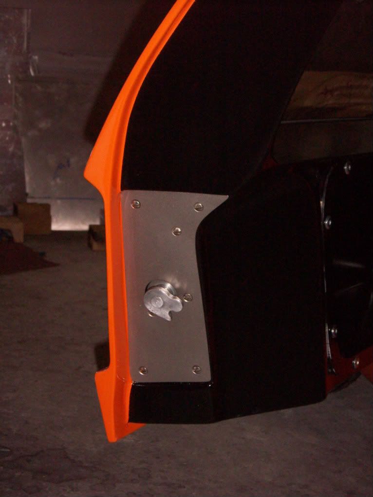
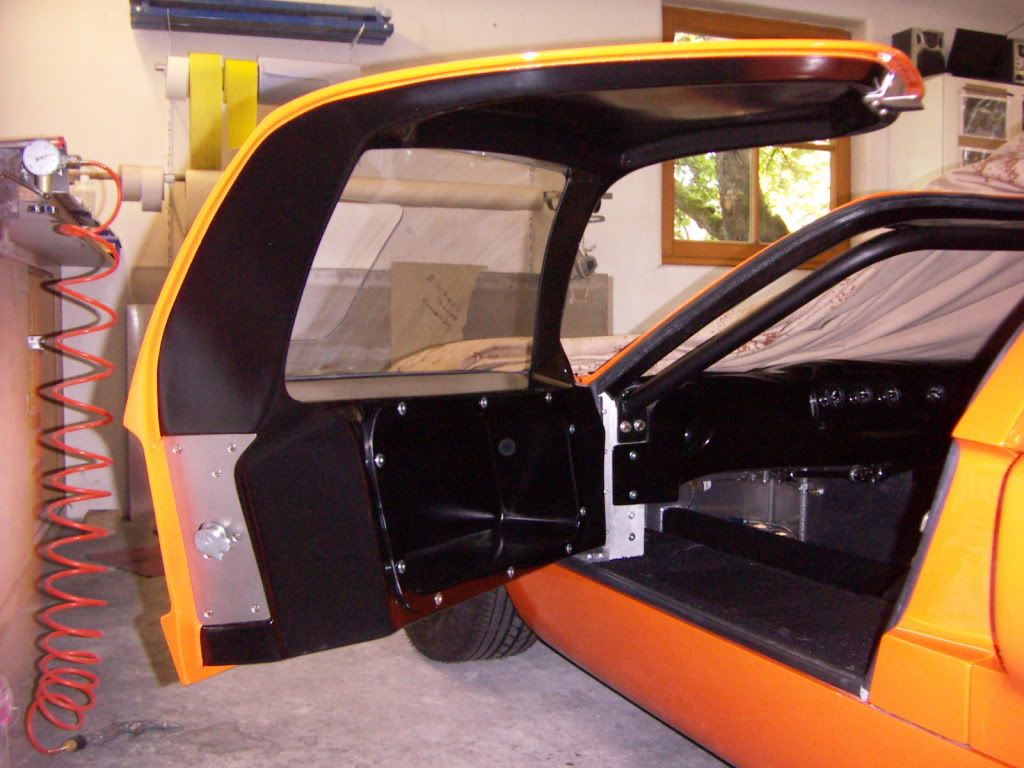
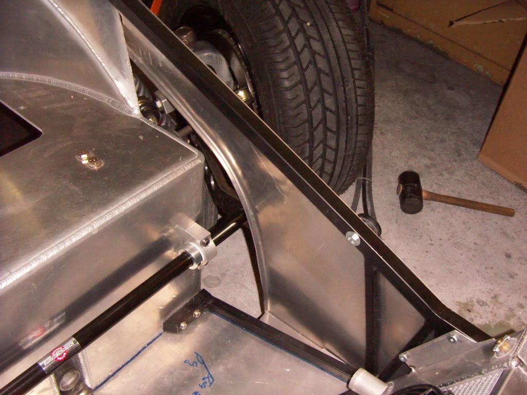
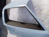
ORIGINALSTYLE PANELING of the front frame:
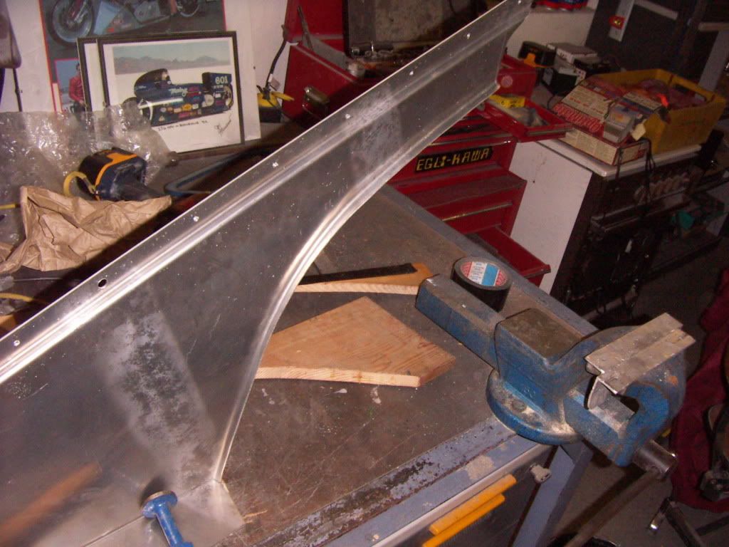
Using 2mm Aluminium i copied exactly what i saw on a lot of pics in my favorite book "TFWBF". After cutting out the shape i bended the top in 2 90°angles to achieve the recess for a perfect fit to the frame ( the rectangular tubes have two different dimensions and so creating this recess). mounted every thing with sheetmetal screws which will be replaced after painting with nice aluminium rivets.
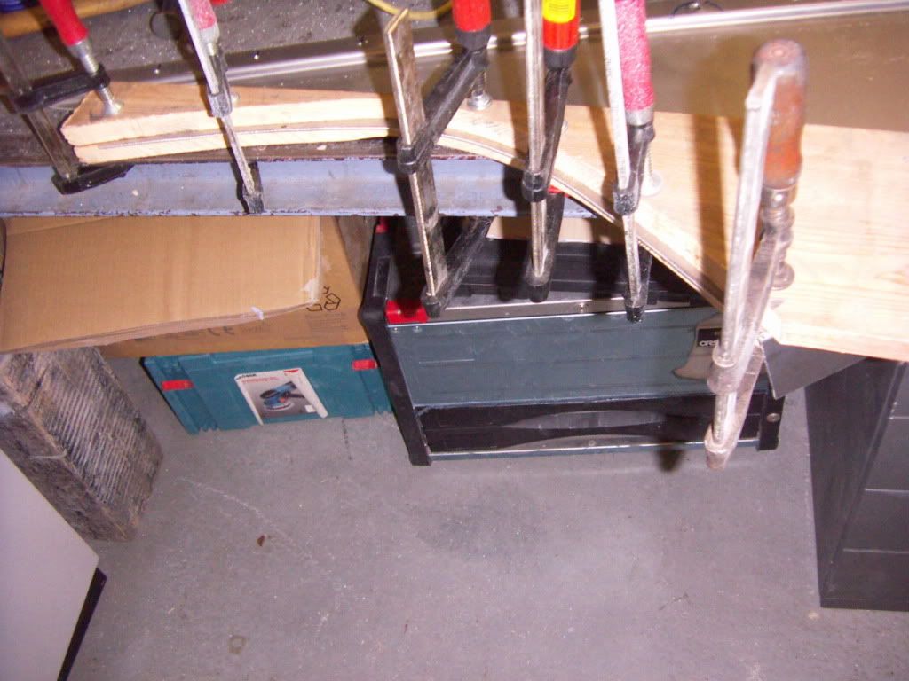
I made a set of wooden templates which i clamped to the alu sheet and hammered the circular bend in a 90° angle to achieve stability and the original look.
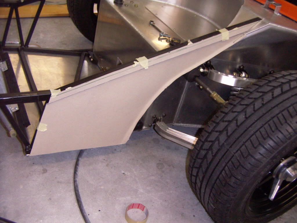
CARDBOARD TEMPLATE
PICT3718.jpg

BENDING TEMPLATES
PICT3720.jpg

FINAL PRODUCT
PICT3722.jpg

FIT
PICT3723.jpg


PICT3729.jpg


PICT3730.jpg


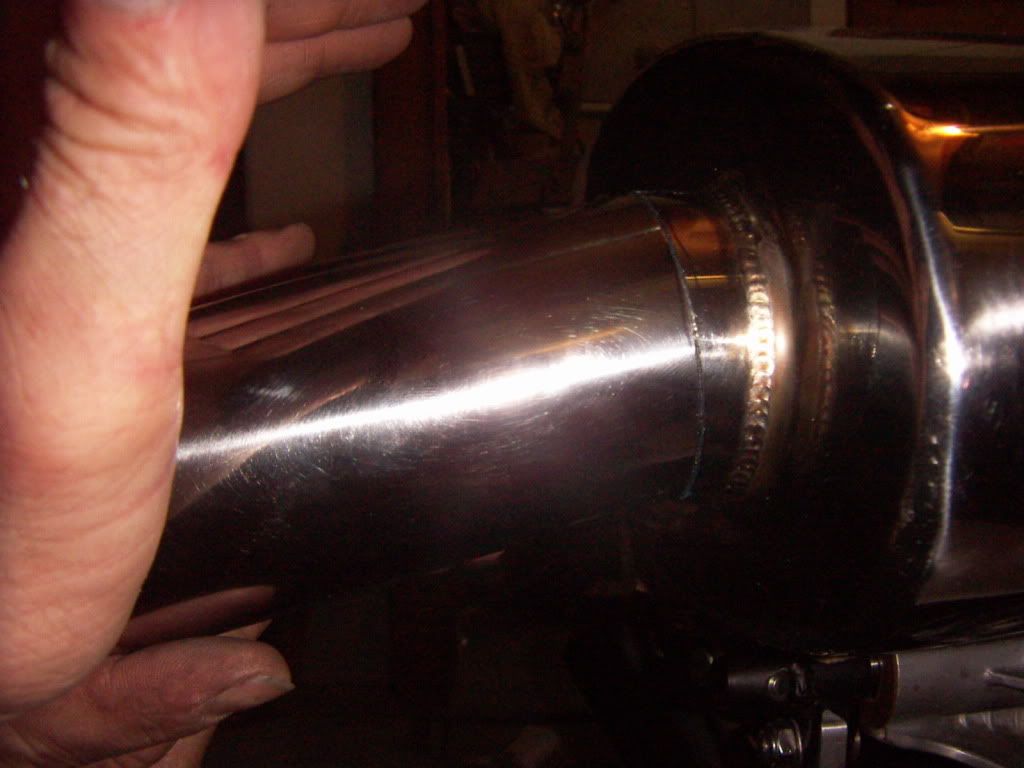
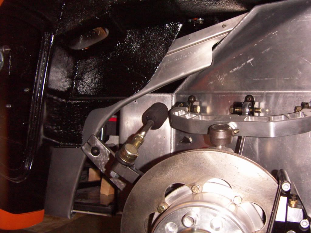
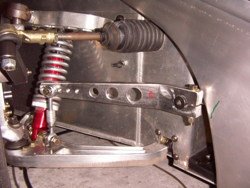
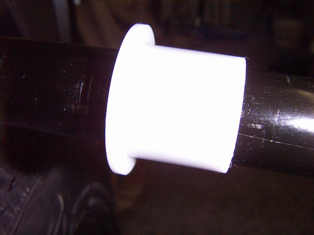
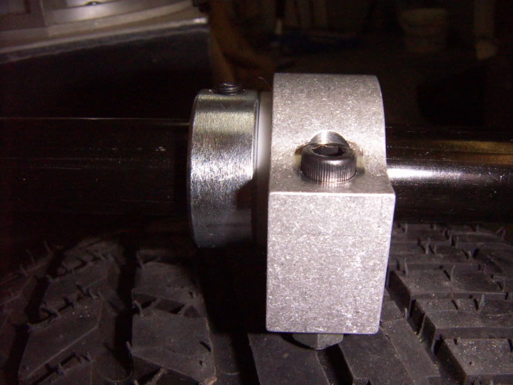
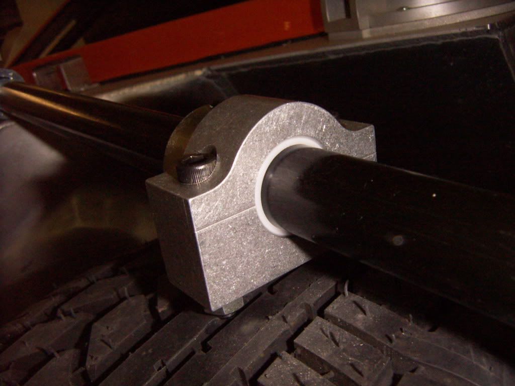
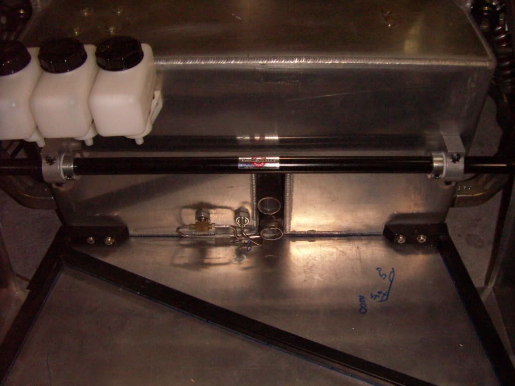
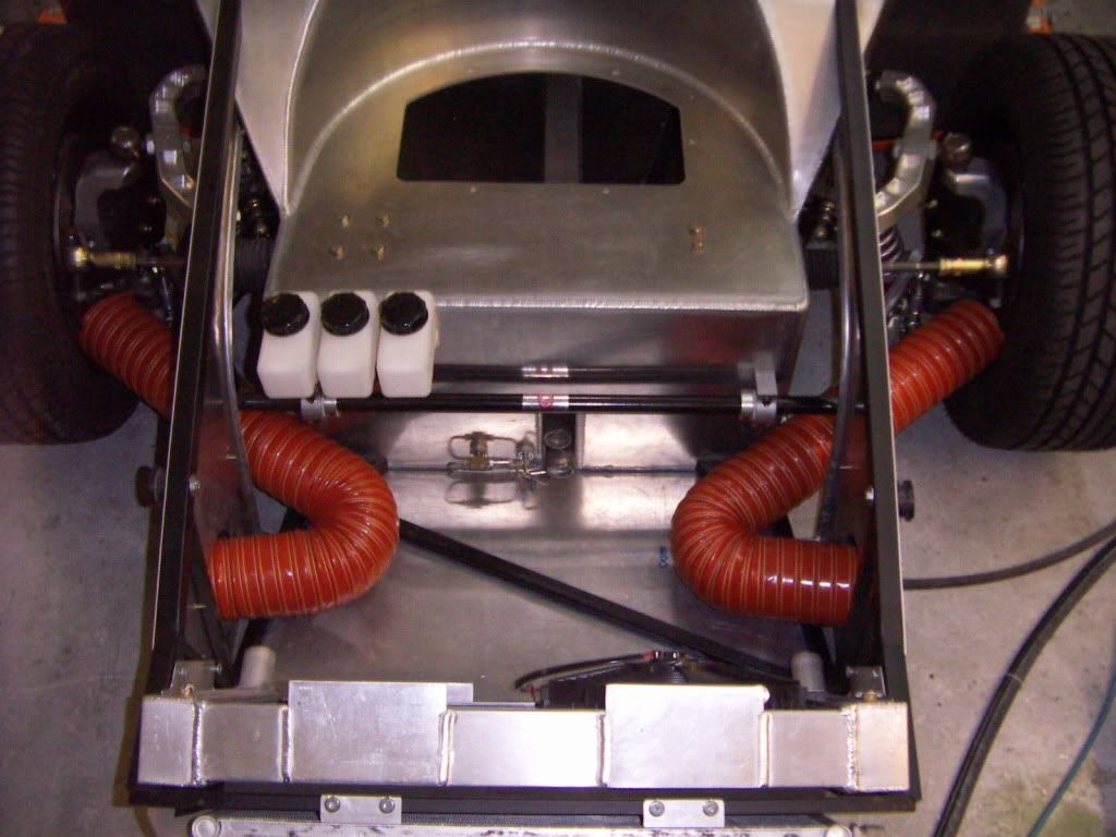
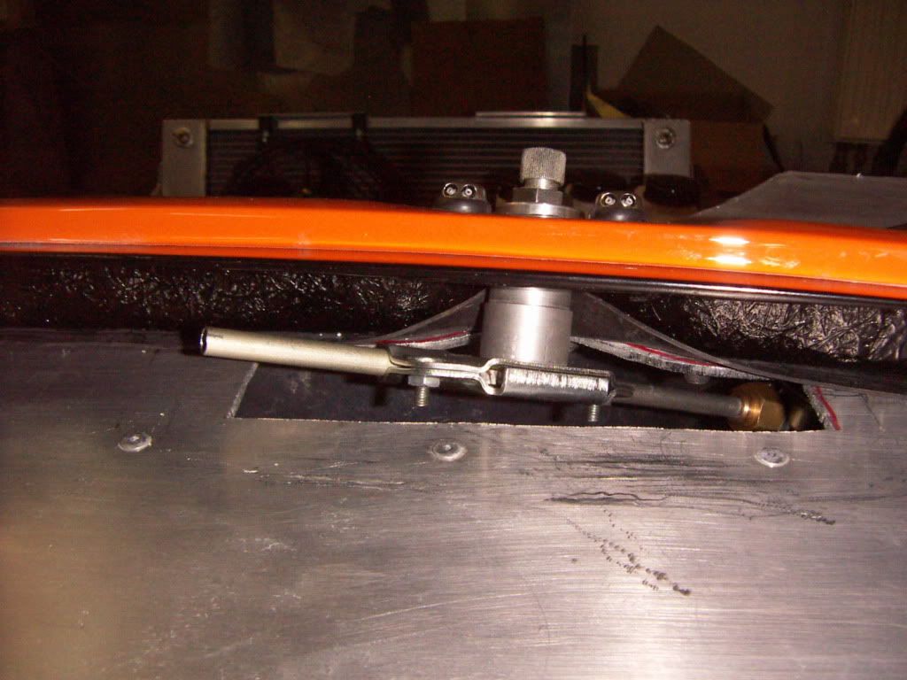
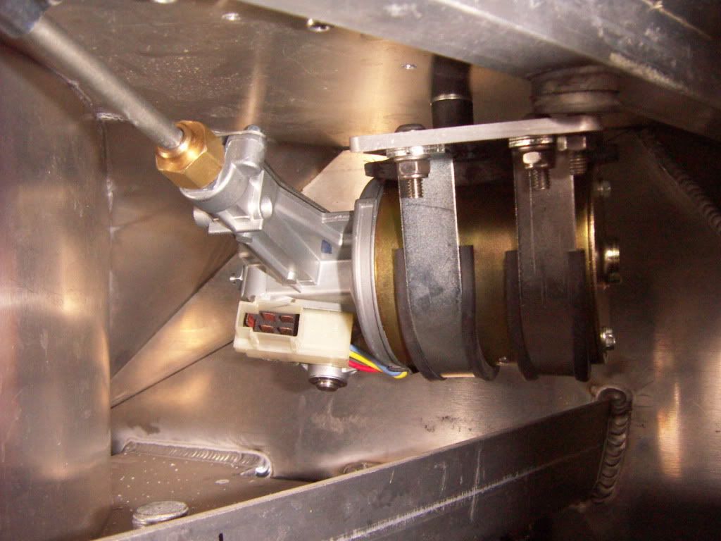
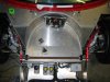
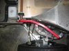
After that i mounted the front sway bar using all the parts supplied by RCR. The arm has to be bend and shortened. I choosed a 32° bending angle and an arm length of diagonal 13". The real operation angle from the mounting point is app 26° giving an operational length of 10.3" inch if i use the middle hole ( out of five) and thus resulting in a wheel rate of app 192 lbs/inch. Adjustability allows from 163 lbs / inch to 282 lbs/ inch at the wheel. (see excel file onby), The sway bar would run directly in the supplied alu mounting blocks. One could grease it but i choosed to open it up in diameter by 4 mm and have had a PU bushing made up. This bushing has also a shoulder where the fixation ring can run on. I also lightened the arm by drilling some big holes.
PICT3727.jpg

PU BUSHING
PICT3726.jpg

COMPLETE
PICT3724.jpg

PICT3725.jpg

INSTALLED
PICT3728.jpg


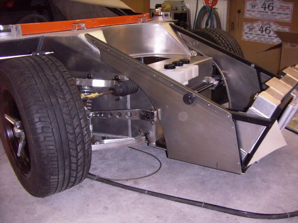
Coolers have been mounted at an earlier stage by using elastic elements for the water cooler. Uising a 5mm thick selfadhesive foam stripe the cooler also is insulated versus the front frame and leans on it.

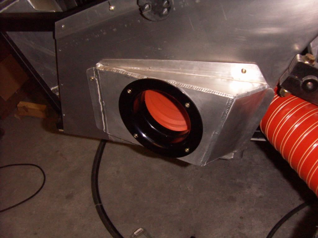
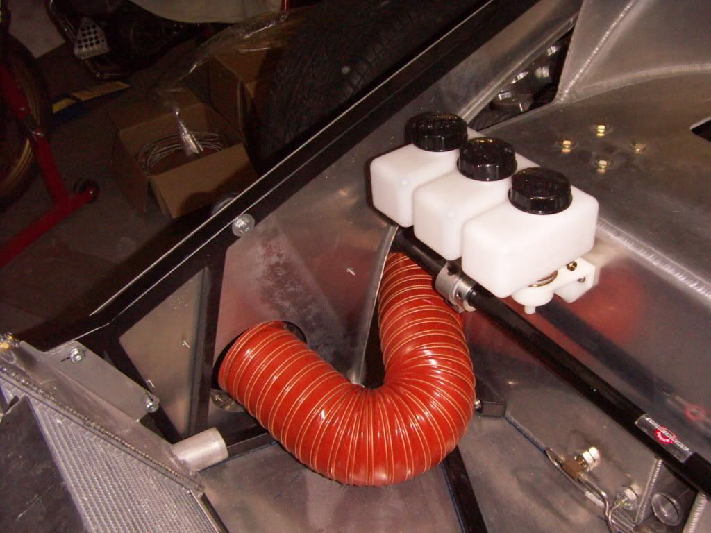
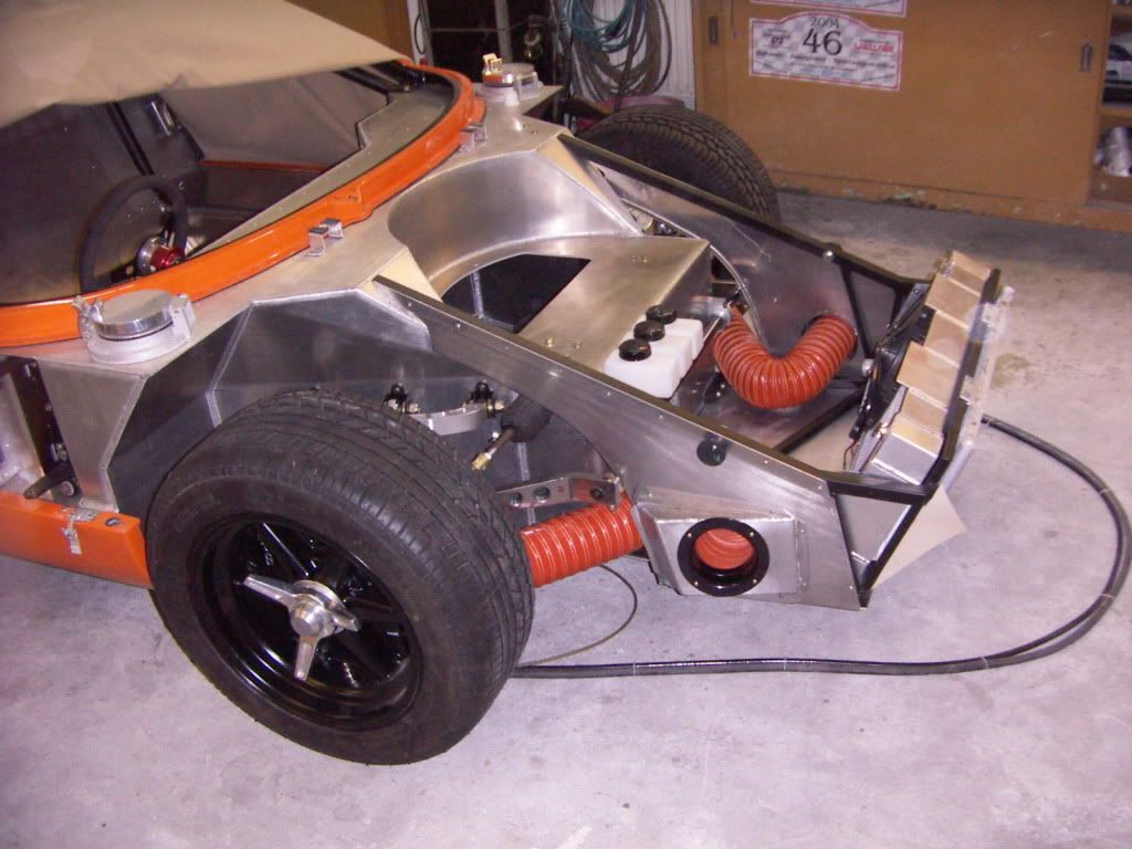
I purchased a set of original brake ductiing adaptors from Jay Cushman ( had no issues at all with the deal) to utilize the originalstyle inner front bodywork of the RCR. I didn´t like the big original 5" hose tube so i modified the adaptor and used a spun black 4" aluminium stack instead to adapt the 4" hose. This adaptors will also be riveted after painting.
PICT3731.jpg


PICT3734.jpg


PICT3735.jpg


PICT3737.jpg


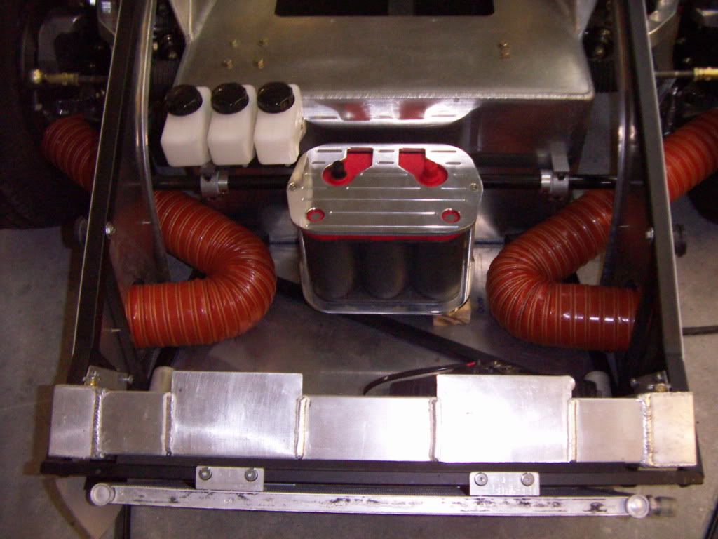
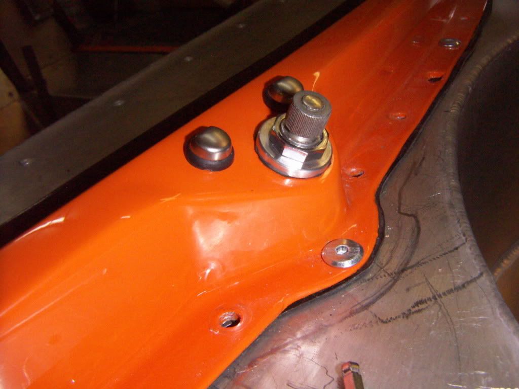
Battery is a optima red top . I placed it in the front, because it changes the weight distribution from rear to front by 2- 3 % and it can not hurt to have more weight on the front tires.
It will be mounted high enough to clear the heater hoses below. It als o clears the sway bar and the single nostril panel. The mount is still to bling and will be black anodized.
PICT3739.jpg


AWH: 560 h

TOM
 

Attachments

  • SUSPENSIONCALCULATIONS.xls
    45.5 KB · Views: 274
Last edited:
Mounting The windshieldwiper:

I installed the supplied Lucas windshield wiper. I figured that the shorter the drive tube the lower the noice and the lower also the maintenance.

I cut out the top dashport to clear the wiper drive and looked for a place to mount the motor which allows a good access, a short drive tube and a installation angle which allows the end tube to clear the rear edge of the dash.

What i came up was this.
PICT3742.jpg


I shortened the original tube to a length of app 3,5 inch. I made myself a little tool to flange the tube again after cutting it.

PICT3745.jpg

PICT3747.jpg


The motor is mounted on a 5mm aluminium plate with the help of the supplied brackets and dampening rubbers.
PICT3749.jpg


This 5mm plate is mounted to the chassis with elastic elements
PICT3740.jpg

PICT3741.jpg


This way i hope it is not to loud. I runned it with a hooked up battery and you could here the noise, but i think as soon the big engine is running , it doesn´t matter at all and is what not resonating sound.
I also made a alu spacer to mount the wiper drive to the spider in the correct height, so that the wiper clears also the washer nozzles.
PICT3743.jpg


TOM

AWH: 565 h
 

Chuck

Supporter
Tom:

Looks great. Two observations:

1. Wiper motor noise will NEVER be an issue as long as the engine is running.

2. Your GT is, I suspect, only the second reproduction car to have windshield washer nozzles. Nice touch. Are you going to use the Lucas washer tank / sprayer???? It looks original and is readily available.

Chuck
 
Status
Not open for further replies.
Back
Top