
You are using an out of date browser. It may not display this or other websites correctly.
You should upgrade or use an alternative browser.
You should upgrade or use an alternative browser.
Transaxle design
- Thread starter jkyle69
- Start date
jkyle69 said:Is their anyone on the forum that has experience of transaxle/transmission design? I am looking at the possibility of starting up a design project to design a transaxle with specific requirements in stages; I am looking for someone who can do this on a freelance basis and work with me to produce a project plan for staged design execution based around the specifications I have. Can anyone give me help/advice/contact for this at all?
I am the designer and developer of the CIMA T906H/S gearbox installed in the Pagani Zonda, Koenigsegg CCX and Apollo Gumpert.
This modular unit can work with diff axle above or below the engine axle, can be H pattern or sequential, synchronised or non an it has the possibility to get into a permanent 4 wd unit.
[email protected] is my mobile e mail.
RTIMTE said:Jim,
I hope you have a lot of cash sitting around as I had the same thoughts. If you want to get the cost down (sales price) you need to produce around 100 units.
100 transaxle cast housings (50,000) for design and initial tooling and about 2000.00 each for a limited production run so 250,000.00
100 sets of shafts, seals etc. expect at last 1500.00 or more like 2000.00 for the shafts and such. so that is 150,000.00 to 200,000.00
100 front engine transmission for Donner gears and syncros 1500.00 each pr 150,000.00.
100 differential's 350.00 to 1,800.00 depending on style and source. 35,000.00 to 180,000.00
100 custom ring gears as it needs to be made with the same machine as making the shaft with the pinion gear at least 500.00 each or 50,000.00
So just to get you 100 transaxle the cost is going to be
250,000.00 +
150,000.00 +
150,000.00 +
100,000.00 +
50,000.00 =
700,000.00 or 7,000 each with no profit
I'm sure I forgot something but as you can see it takes a lot of capital to just produce 100 of these things and the price per is already 7,000.00 each with no profit.
Too much semplicistic calculation with the intent to demotivate the guy.
There are exhisting gearboxes which need to be only redressed in order to meet the cardinal points.
I am sure we can reach the goal, dear Mr Timte ( gearbox manufacturer )
Regards from another gearbox manufacturer.
Wanni,
In another thread, you referred to hydraulic pitting caused by oiling directly into the entry of the gear mesh, and state that it's not a race box.
Are you saying that for a race box you would spray onto the entry (and accept any long term hydraulic pitting) but for road applications you would spray onto the exit?
Whilst this is a consideration in the design of a new trans there are of course many guys that fit additional oilers to their existing trans. Could you please outline the pros and cons of entry/exit spraying.
Cheers,
Russ,
as you know the surfaces after the machining are not perfect and they show "hills and holes". By spraying in entry you force the oil in between the teeth which have an enourmous load. The oil is not compressable and the "oil drop" by not excaping will generate a point of load concentration. Once, twice,.....and the pittings gets out. Especially with standard steels which have big hardeness gap,s between the carburised zone and the base of the steel. On top of it this generates an oil over heating.
By spraying in exit with the spray origin as close as possible to the pinion ( sually is to high out of the oil, and the crown wheel is generally operating in a dynamic oil level )teeth, is cooling down and that's it.
Again, racing purposes are different that street purposes.
Racing: it shall work for only 3 hours outstanding the best performances.
Street: it shall work fine for life keeping the losses as low as possible.
Ciao
Wanni
Wanni
The ZFQ feeds the return oil to the exit of its crown wheel and pinion so cavitation or hydraulic pitting should not occur.
Regards
Chris
Well done, my friend, but why you bring it pubblic only when you are in trouble.
I started to supply suggestions free of charge, in order to help you to do not put your feets into a shit.
You did not appreciate my irruent help, which was finalised exclusively to trace a way to follow in order to avoid future troubles.
Great respect for Quaife and for your knowledge......but I am OEM supplyer with some rules and ethics to be performed.
You are free to do whatever you like but please do not turn the cards on the table. Be transparent.....as I am. Everything is sold from me is pubblic and clear. If you feel upsetted for my suggestions,,,,,my friend you are in the wrong direction.
Think about
Cheers
Wanni
Just to stir things up, ther is another alternative that I haven't seen mentioned - the Weismann.
New Page 1
And yes, this is race transaxle, but it has a very long history - and a 12 bolt Chevy ring & pinion - which has less pinion offset than a 9 inch ford.
If I could afford Wanni's box, I'd probably at least be interested.
David
New Page 1
And yes, this is race transaxle, but it has a very long history - and a 12 bolt Chevy ring & pinion - which has less pinion offset than a 9 inch ford.
If I could afford Wanni's box, I'd probably at least be interested.
David
Well I sat and watched as long as I could stand and now its time.
I am not the first to think of this but take your bellhousing of choice
and then bolt a Quick change rear end directly to that.A simple remachine to a input shaft and you are complete to this point.Now it gets interesting- take an adaptor plate and bolt a T5 case to the back of the housing.Now make up a housing to place the original QC gears in and send the power back to the ring and pinion.Now all of your gear problems are solved as ratios are just about unlimited. There is no shortage of high perf parts for these trans and any cast orsteel bellhousing for ANY engine you choose is available.You are also no longer bound to expensive clutch and pressure plate combos so any decent speed shop will have you up and going in no time.Other than the clutch input shaft and a few other machined parts there are no terribly hard to acquire parts here.If you look at the T5 its not that long when you get rid of the unnecessarilly long input and out put shafts.Use your imagination and you will see it come together.Any moron with basic hand tools can rebuild a T5and if you remain with a bolt on assembly for the trans it could be removed and replaced with a back up unit in less than ten minutes.Shifting could be handled with simple linkages.There are late model QC rears for sale all the time and any thing from spools to ratchets are available.
Give it some thought people as I plan to build one myself.
REMEMBER these rears handle some extremly high HP situations and if you do break a part its usuall the QC gears...... and they are cheap!!!!!
Maybe I am a idiot but these parts survive with extreme HP every day and they are readilly available and easilly serviced.
If you like my ideas tell me and if you decide to try this keep every body informed of your progress.I allready have several ideas for parts and mods so ask questions and I will try to answer them.Maybe this will become the holy grail of the transaxle game that you have been searching for........
JUST THINK ABOUT IT.
Now that you have thought of it, go out to your pile of bits, measure them up and work out these three critical distances.
1. The distance from rear of engine block to output shafts of transaxle.
2. The distance from output shaft to rear of your intended transaxle design.
3. The distance from the centerline of your input shaft to the centerline of your output shaft.
Now superimpose a drawing or template of this combination on your GT40 of choice & let me/us know how you got on. Good Luck.
One other thing for your consideration- Have you thought about the torsional load that you are going to impart to the donor transmission case when you mount your QC housing onto the rear of it. I am not saying it wont work, just trying to help-I'm good like that.")
Jac Mac
1. The distance from rear of engine block to output shafts of transaxle.
2. The distance from output shaft to rear of your intended transaxle design.
3. The distance from the centerline of your input shaft to the centerline of your output shaft.
Now superimpose a drawing or template of this combination on your GT40 of choice & let me/us know how you got on. Good Luck.
One other thing for your consideration- Have you thought about the torsional load that you are going to impart to the donor transmission case when you mount your QC housing onto the rear of it. I am not saying it wont work, just trying to help-I'm good like that.
Jac Mac
Ron Earp
Admin
It'll work, but it comes out far to long for a proper GT40. There is an example of this somewhere on the forum.
Some fellow was building some big GT40s and rigged up a standard small automatic transmission and rear diff. He then found it was far too long and used pulleys and cogged belts to take the output from the diff back up to the wheel openings. And his wasn't even a correct shape GT40, it had far more freedom.
Some fellow was building some big GT40s and rigged up a standard small automatic transmission and rear diff. He then found it was far too long and used pulleys and cogged belts to take the output from the diff back up to the wheel openings. And his wasn't even a correct shape GT40, it had far more freedom.
Wedge,
To make it easier for you;
1. The maximum distance from front of Waterpump to center of output shaft is around 32" / 33" before you have to start beating on the firewall of a GT40. ( Fitted height of motor is a factor here, the lower the better ).
2. The rear of the TA should be no more than 20" back from output shafts on a Mk1, around 23" on a Mk2, & up to 29"/30" on a Mk4.( You can of course trim the rear clip & poke the TA out the rear further if the aesthetics dont worry you - The Mk2 is a classic example)
All the above assume outputs in line with hub centers vertically.
Jac Mac
I am just starting to acquire the parts to build this. I will make every effort to make the assembly as short as possible.I may mill the trans mounting surface off and gain a few inches there . While I appreciate your measurements i woulld prefer them from the bellhousing flange back as this is a non changing surface unlike the waterpump.This may not work for an exact resto but for a kit you should be able to take a few liberties I am sure.Another option to use a slightly longer transaxle like this would involve a small reengineer of the water pump area itself. ORRRR a guy could change his parameters slightly and install a supercharged V6 or a turboed engine.Ultimately the idea is to build this transaxle and whatever engine assembly that we decide on and build a car around it. If when we are done the GT40 body fits that would make us extremely happy. Now then when they ran the FE style motors they were obviosly longer than the windsor series . There has to be a little wiggle room available.
Dont be afraid to keep me on my toes as no man thought of everything even though as a man I could never admit it.
Dont be afraid to keep me on my toes as no man thought of everything even though as a man I could never admit it.
A quick reread of your post Jmac leads me to believe that you think I am mounting the trans ahead of the quick change when I am actually rear mounting the trans. As for torque this is something that I have thought about and have a few ideas on how to adress. Some of my ideas are out there but this will not cost me a lot of money to prototype.I have a friend who runs an A fuel dragster and things like 300M shafts and the like are not that hard to come by as he has ordered this stuff from both prints and from sending in a cobbed together shafts for them to reproduce.Mr earp I also seen the belt drive idea and I feel that its not practical. I honestly believe that I can come within about 2 to 3 inches of the bellhousing to center of output based on the pics I have seen.If you look at the input shaft on the quick change then you will see that the engine position will be very low indeed.
Attachments
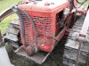
By the way ignore the pic I just threw that in to see if I could so I could show you some drawings later.This is my other toy that I use on the toys that dont work. Kind of like monster garage.
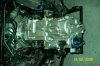
Well I went out and sourced myself a quickchange rear end this weekend and now I think I have what I need to get started.I have seen this picture before J Mac and while it gives me some ideas I actually hope to do a more compact design and improve upon it.(Dont we all)By the way did anyone come up with the bellhousing flange to center of output shaft measurement? Another thing that I would like to know is the weight of the standard transaxles in the original GT40s and the weight of the other transaxles that are being used to give me a goal to shoot for. Lets face it nobody wants this to be half the weight of the car.
Re: T44
GEARFOX TRANSMISSION CONCEPTS SrL
54a, via VOLTA
I - 40014 CREVALCORE (BO)
+39 335 5953275
[email protected]
default
GEARFOX TRANSMISSION CONCEPTS SrL
54a, via VOLTA
I - 40014 CREVALCORE (BO)
+39 335 5953275
[email protected]
default
Similar threads
- Replies
- 21
- Views
- 2K
- Replies
- 11
- Views
- 1K
- Replies
- 1
- Views
- 598
- Replies
- 7
- Views
- 2K