velocity stack filters

Buzz,

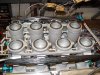
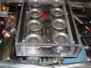
The filters you are using are folded like most K&N filters. If you took them apart and stretched the filter cloth out flat, you would find the actual area is a lot more than the cross sectional area of the filter assembly.

The system your builder worked out is a very good idea. The big problem with Webbers has always been that you can’t see them if you put a filter on them. (Of course, you couldn’t see them on the original cars because they had a plate above them, but that was for other reasons).

Kevin
 

Ian Clark

Supporter
Buzz, Very cool looking air box, great WOW FACTOR! You also got me going on the reversed NASA duct on the roof, what's the story here? You have a ton of real neat stuff in your car, keep up the good work!
 
Hi Buz, Great idea and looks great too. Does the box fit tight enough to create an air dam to keep the heat down and only the cold air at the top getting into the carbs? Joe
/ubbthreads/images/graemlins/confused.gif
 

Chris Duncan

Supporter
""I wondered about installing custom made filters in each side inlet of the body. Then sealing the stacks with a turkey pan such that when the rear deck is down all of the air must come through the two side inlets.""


I was thinking about this also, it would be pretty tricky to seal the cold air box but it would probably be doable, although the ducts look so nice coming in the side with no restriction.

Regardless of what's done it should be a sealed cold air intake system with the cool air coming in the side ducts.

Finally found what I was looking for at a good price, individual K&N's ,won't be able to see those pretty TWM stacks though, probably take them off for the car shows.

4" tall by 3-1/2" dia. for $140.00 the set of 8 at Speedway Motors.
 

Pete McCluskey.

Lifetime Supporter
Great idea Buzz, really looks the ducks nuts. Like Joseph I am curious to know if the bottom bit fits tight enough to
keep the hot air out. Do you have a diagram/drawing you could post?
 
kmcgowen:

Thanks for the little filter tutorial.

I'm concerned about the "spit-back" of fuel from the stacks onto the inner surface of the Lexan. Is that a reason for the plate over the Webers. Both my engine buddy and the head tech at Hilborn thought "spit-back" was a non-issue with this injection. Hours on the dyno under hard pulls seems to support the non-issue side.
 
Kalun D:

I decided against the idea of sealing the sides as part of an air box for a couple of reasons...some technical...some practical.

First off was that I can't take the risk of no filtration. I don't like the simple idea of an October drive in the Northeast with swirling leaves sucking into those rear vents towards my open stacks. So filtration is an absolute for me because I will get 20,000 miles on the car the first year.

Cold air versus warmer air is another issue. Fron a practical standpoint I'm past this issue. There are a lot of 40s out there that are running fine with 350 to 600 HP. Rick Merz has 20,000 miles on his car, has run to 190+mph, and does 11.7 to 12.2 in the quarter. Therefore, I don't "neeeeeed" a sealed air box for added performance.

On the other hand, I wonder if anyone has done any air flow testing to determine the effectivness of the side vents. To answer my own technical question, I am going to watch the air flow through the side vents a different speeds by taping two inch pieces of string or yarn just inside the vents so they hang down. It is possible that at some speed the pressure under the car and flow into the engine side vents creates enough pressure that air going over the engine flows up and into the induction system. Imagine the surprise if those little pieces of yarn are blowing out of the side vents at some speed.

Food for thought!
 
Canuk40:

Good eye Ian, and thanks for the complement. I'll get something going on another thread about the car.
 
Joseph &
Pete ("the ducks nuts", there's a vision)

Here are a couple more pics to show the sealing. There is a lot of machining involved, but no drawings....holes bored for the 8 stacks through the bottom plate....groves machined in the top and bottom plates to accept the "flair" at the edge of the filter....mounting hardware fabrication for the top to bottom, and different for the end caps....perfect fit for crush of the filter flair on the side panels with no air gaps left at the end caps. Lots of hours there thinking and fabricating.
 
This one shows the O rings that the bottom plate sits on to dampen vibration, and avoid leakage from underneath.
 

Attachments

  • 33641-sm356.jpg
    33641-sm356.jpg
    76 KB · Views: 442

Chris Duncan

Supporter
Buzz,

Agree, there must be filtration. And also agree that hot/cold air is not that big an issue unless you want a full on race effort. Just like the difference between equal length headers and non which is less than 5 percent, hot/cold is probably the same.

Believe most of these cars build pressure in the engine bay, you shouldn't have any problem getting air to the intake. The original design had a sealed cold air intake so you would always have flow coming in the cold air vents.

Heat might affect carbs more than injection, not sure.

All that said I think the cool air intakes are part of the "art work" of the car and like them being functional too.

Your work looks great though, where did you get filter elements and how much were they?
 
Here is some better detail.

Bottom plate sits on black O rings.
Stacks go through plate and o ring to sit on a lip about one half inch down inside the manifold. Stacks are then pinch clamped at the manifold.
Silver silicone caulk is a temporary fix to get the engine on the dyno. The caulk is holding/sealing the stack to the bottom plate from inside the box. It is hard to see in the pic that ther is silicone, Lexan, and then the O ring. The silicone will be removed and clamps will be made to secure four of the stacks to the inside of the bottom plate.
Five small allen head screws are machined to secure each end cap along its bottom edge.
Six stands were machined for securing the top to the bottom.
The only place that you can see the machining for the "flair" is if your eye follows the top of the end cap to the corner until you see the relief cut into the end cap to accept the end of the flair. A similar grove is cut along the length of each side of the top and bottom plate so the flair can set down in the grove.

Pete...now its "The Ducks Nuts"

Enjoy....
 

Attachments

  • 33646-sm398.jpg
    33646-sm398.jpg
    80.8 KB · Views: 436

Howard Jones

Supporter
What a wonderful idea! I love the clear airbox! I would keep it even if it didn't quite pencil out at max power.

Another thought. A TRANSAM road race motor makes about 700 hp and is a smallblock single 4 barrel motor. The Carbs flow about 800 cfm and I am sure those guys have done the r&d on the airfilters.

I took a long look at several transams cars at longbeach last year and I am sure they are all using something like a K&N 4"X 12" or so round filter inside a airbox drawing its air from in front of the windshield.

I think you will be ok on CFM through the filter you have made.

Good Job!
 
Thanks Howard!

Initally I thought this would be built with filtration all around. Then I told my buddy I wanted to see through the rear view mirror and down between the stacks. All along he has indicated that CFM was never going to be a problem. If we had more time there would have been even less filtration area and more see through.

He designed the engine with the Jesel system and some titanium retainers to take 8500RPM even though I wanted all the HP and Torque in by 6000. They were both over 500. He ran the motor out to 7,000 even though peak HP was at 5800. So no CFM problems...I was just curious about some of the calculations mentioned.
 
Buzz,

As best I have been able to determine, the V shaped plates on the original cars are an after effect of the infamous 1964 LeMans “Cherry Pit Incident” in which someone apparently dropped a cherry pit from the public balcony over the pits and it fell into one of the Weber carbs on the Hill / McLaren car causing them to make 5 pit stops during the first hour to try to resolve the problem.

As for Reversion or “Spit Back”, an injected set-up will have less of a problem than a carb, but in an IR manifold you will probably always get a little. Fuel injection in real life is nothing like the idealized pictures they show. You generally still have some wet flow and a partial “Wet Manifold” situation with most types of fuel injection.

A quick example from an entirely different area. The Lycoming IO-360 Aircraft engine is port fuel injected with air fed from a single, branched intake manifold. In aircraft engines you generally monitor both cylinder head temperatures and exhaust gas temperatures for all cylinders. Pilots noticed that they were getting uneven readings with this engine, which made no sense given that that was one of the main problems the fuel injection was intended to cure. After some careful study Lycoming found that fuel was being moved by reversion pulses inside the manifold from one cylinder to another causing a mixture imbalance even though it was port injected.

Having said this, reversion is not likely to be serious enough to require anything special as far as your engine is concerned. The final test is always to dyno the engine with EGT probes in the headers a few inches down from each exhaust port. You tune to get as close to even temperatures as possible.

Kevin
 

Pete McCluskey.

Lifetime Supporter
Thanks for the detail Buzz, a really terrific idea. I'm off
to show this thread to my engine builder. /ubbthreads/images/graemlins/smile.gif
 
Pete:

Two words of advice.

First....that freshly machined Lexan was like a razor. The same corner sliced up two of us before we took the thing apart to machine all the edges.

Second....measure, measure, and then measure some more, or when that engine goes in you'll have some unpleasent moments. Then be ready for more surprises when you lower the rear bonnet. (that's down under talk for that big trunk lid behind your driver's seat)

Remember if it works and you love it....there is a licensing fee.

Buzz

PS. There's a pretty little worked R90S BMW that keeps the ugly old Knuckle company. Sort of like my social like.
 

flatchat(Chris)

Supporter
For some reason due to aerodynamics or pressure zoning???You get alot of very hot air off the exhaust blowing over the back end of the motor,so, some sheilding b'tween exhaust at the crossover and the rear of the intake would be necessary unless you want melted lexan all over the place
I use a sheet of alluminum 1mm thick that fits b'tween the rocker covers the top of the bell housing and the underside of the rear clip-- works for me!
Good luck .Chris /ubbthreads/images/graemlins/cool.gif
 

Tim Kay

Lifetime Supporter
Buzz, (if your listening)

I am interested in making an air box similar to what you have and was curious how your air box worked out. Are you still using it and is it sufficient filtering and cfm?
 
Back
Top