What block preparation is required for dry sumping a SBF?

Sandy

Gulf GT40
Lifetime Supporter
I can't remember if also for the Ford block (I have a Dart block aluminum block as well) it was mentioned that if the sleeves were not above the deck on receipt of the block from shipping to contact them. I'll see if I can find the paperwork. Might not matter as sounds like you are going to have to do a surface on the deck, but good to know for the next one :)

Really nice work on the Daytona as well!

Sandy
 

CliffBeer

CURRENTLY BANNED
jac mac said:
Cliff,

You have not taken into account that your Ferrari @ 3.2 litre or 3.6 litre is only going to have from 400/450 cc per cyl. In order to have this it will have a shorter stroke or smaller bore or combo of both than the 5.0 litre(302 cu in ) Ford with 625cc per cyl. The reduction of weight of the smaller rods/pistons is what allows ferrari to achieve a relatively smooth 180 deg engine. It is also interesting to note that in the lancia application that they revert to 90deg configuration, perhaps to appease the not so sporty drivers who may demand a smoother running engine as opposed to the ferrari driver who i imagine loves hearing his exhaust note and accepts the slightly harsher characteristic as part of the package.

I should also point out that if your GT40 has a crossover exhaust system with 180deg firing intervals its exhaust will be similar to the Ferrari but deeper and more "Authorative " due to the larger capacity of each cylinder.

Jac Mac

Jac Mac, if I understand you correctly above it seems your point is that the geater displacement of a flat crank SBF will produce a proportionately rougher running engine than the ferrari, is that correct? If yes, I do not agree because the proportionally greater mass of the SBF tends to damp and absorb the vibration. The SBF outweighs the 3.2QV by about 165lbs. One real world data point I have (amongst others) is this: the cosworth V8 is a flat crank design and I have run these in my race cars before w/o undue vibration.

And yes, the Thema had the 90 degree crank because it undoubtedly runs smoother and this better suits the Thema demographic. My point above is not that one is smother than the other - this is obviously true - my point is simply that the flat crank is only very slightly rougher running provided there is good balance to the reciprocating pieces.
 
Cliff, I think Jac was talking about the reciprocating assembly, eg the rods and pistons being lighter, therefore offering less vibration than the SBF large rod/piston weights. I dont think he was referring to the overall engine weight, although block weight may have a small dampning effect.
 

Russ Noble

GT40s Supporter
Lifetime Supporter
As I understand it there is an inherent out of balance factor in a flat plane v8 not necessarily manifested in vibration. The smaller the motor the smaller the out of balance forces. How long was the relatively small Cosworth DFV run between rebuilds? If a flat plane crank in a largish V8 was a good thing, everyone would be running them. Bigger V8's with flat plane cranks were regarded as sprint motors only. They were tried by some guys in F5000 in the 70's but whilst sometimes quick they were generally unreliable. There will be people with better memories and information than me but that was my perception from that time.

Cheers
 

Pat Buckley

GT40s Supporter
Interesting thread, thanks!

Since it has strayed somewhat, I don't feel bad asking a question that isn't related to dry sumping .....

My CAV has a 302 crossover exhaust but the engine came with a cam that has the 351 firing order.

2 questions:

1. What effect will this have on power output?
2. Will this make it difficult to tune a set of IDA's?

Pat
 
RamboLambo said:
Cliff, I think Jac was talking about the reciprocating assembly, eg the rods and pistons being lighter, therefore offering less vibration than the SBF large rod/piston weights. I dont think he was referring to the overall engine weight, although block weight may have a small dampning effect.

Right on Rambo Lambo, Cliff as well as the smaller/lighter components in your DF-- or Ferrari, the cyl bore centers are closer together. In the small motors this reduces the rocking couple that is present in the front pair & rear pair of cyls on each bank ( a total of 4 rocking couples in a V8 Flatplane assy ), In the Ferrari/DF-- motors the bore centers are about 3.85" while the SB Ford is 4.38".

Jac Mac
 
Pat said:
Interesting thread, thanks!

Since it has strayed somewhat, I don't feel bad asking a question that isn't related to dry sumping .....

My CAV has a 302 crossover exhaust but the engine came with a cam that has the 351 firing order.

2 questions:

1. What effect will this have on power output?
2. Will this make it difficult to tune a set of IDA's?

Pat

Hi Pat
As you say, interesting subject! Thanks Russ for the right link where we can find some interesting point of view:

JCoop said:
Correct me if I'm wrong but the 351 based motors do not have the same firing order as the 289/302/460; which I'm told the bundle of snakes 180degree exhaust system was designed for. It wouldn't sound the same and the pulse-extractor effect wouldn't apply, I think. My 302 w/Webers sounds wildly awesome as compared to a friend's GTD w/ 351 @ 4500 RPMs.
Sandy said:
I had asked the firing order question a long while ago too (302 vs 351) and I think it does not matter. I think the question came up as I run 351 firing order (in a 331) in the mustang and most of the roller cams that I had were that way as well.

1-3-7-2-6-5-4-8 Late 5 Oh's, and 351
1-5-4-2-6-3-7-8 Early SBF's
(I hope I got them right...)

I guess the easiest way is to look at the pipes and collectors and map to the above and see if it seems like it would change the effect of the bundle o' snake. My guess not really. My mustang has a Dr. Gas X Pipe on it (regular car headers) and it is very Gt-40'sh sounding.

[edited]

If this helps, it looks like the headers on my engine are mapped like this (hard to tell from the pics but looks like this) -

Left Right
8 - 2 7 - 4 Top
| x | | x |
5 - 3 6 - 1 Bottom

Looking at the rear of the collectors from the back of the car. The number is cylinder of engine it connects to.

Sandy
It is a common agreement that exhaust pipes must be grouped by 180°. However, in order to have the best "pulse-extractor effect " as mentioned by JCoop, it is necessary to have a circular pipe arrangement according to the order. It means that for a SBF engine with a 302 camshaft the ideal merge collector arrangement should be modified as follow: (I refer to the nice data from Sandy)

Left________ Right
5 - 2 ......... 6 - 4 Top
| x | ..........| x |
8 - 3 ..........7 - 1 Bottom

You note that with this new arrangement the circular order is clockwise at the left side and anti clockwise at the right side.
With a 351 camshaft the ideal merge collector arrangement will be as follow:

Left________ Right
5 - 2 ......... 6 - 4 Top
| x | ..........| x |
8 - 3 ..........7 - 1 Bottom
This data is the same like the 302. However, in this case both circular orders will be in opposite to the 302.
To conclude, we note first that the Sandy's merge collectors have not a circular order for a 302 cam. In second, I agree with Russ, whatever the camshaft that you use (302 or 351), it doesn't affect power nor Weber tuning, except if your circular arrangement is like Sandy. In this case, we note that it could be correct at one side (left) and incorrect at the second (right) when you use a 351 camshaft. That means you will have a different pulse-extractor effect at one side that will affect power... and Weber tuning :eek:
Hope to be clear despite my language problem ;)
 

Sandy

Gulf GT40
Lifetime Supporter
Damn, I'm going to be down some hp :grinf: , but not to worry I don't have webers so that part is ok!

[edited]
Now that I think of it, why do the have to fire in a circular order, does that help? Will the distance of the diagnals (1.4x center to center worse case) make a huge difference, especially in the collector (or merg collector) area?

Sandy
 
Last edited:
Sandy said:
[edited]
Now that I think of it, why do the have to fire in a circular order, does that help? Will the distance of the diagnals (1.4x center to center worse case) make a huge difference, especially in the collector (or merg collector) area?

Sandy
By firing or pulsing in a circular manner the signal is the same for all cylinders, the merge collector is suited to the even 180deg pulse, while the larger volume collector typical of most conventional non crossover exhausts helps accomodate the uneven pulse's. You will also find that with the 180deg system you can use a smaller dia tailpipe than you will require with the conventional type. (270/180/90/180) pulse interval's.

Jac Mac
 

Russ Noble

GT40s Supporter
Lifetime Supporter
jac mac said:
By firing or pulsing in a circular manner the signal is the same for all cylinders,
Jac Mac

The theory is good but how much difference do you think you would be able to measure on a dyno?

Cheers
 
Russ Noble said:
The theory is good but how much difference do you think you would be able to measure on a dyno?

Cheers

If there is a difference - some.
If there is no difference- none.

Cheers
Jac Mac
 
Sandy said:
Damn, I'm going to be down some hp :grinf: , but not to worry I don't have webers so that part is ok!

[edited]
Now that I think of it, why do the have to fire in a circular order, does that help? Will the distance of the diagnals (1.4x center to center worse case) make a huge difference, especially in the collector (or merg collector) area?

Sandy
Sandy, when you try to empty quickly a bottle of water, you give a circular movement at the bottle that will create a mini wirlpool inside to accelerate the empty operation. Exhaust pipe circular arrangement follows this basic principle. Whatever your induction system (carbs or injection) this design is in relation with your camshaft characteristics and your induction tuning. However, don't worry, there is not a large difference between all different arrangements. My purpose was only to indicate the best theorical way ;)
As a small sketch is better than thousand words (mainly for me :eek: )
please have a look below
 

Attachments

  • ordre des tubes 302.JPG
    ordre des tubes 302.JPG
    29.7 KB · Views: 463
  • ordre des tubes 351.JPG
    ordre des tubes 351.JPG
    29.3 KB · Views: 444

Russ Noble

GT40s Supporter
Lifetime Supporter
jac mac said:
If there is a difference - some.
If there is no difference- none.

Cheers
Jac Mac

As I've said before Jac Mac, you're a mine of information!

I'll stick my neck out and say that IMHO there will be no significant difference shown on the dyno.

That should get me shot down in flames! Someone's bound to have 10 repeatable dyno pulls with and without circular flow that they've averaged out to conclusively show there is a difference!

Cheers
 
jac mac said:
By firing or pulsing in a circular manner the signal is the same for all cylinders, the merge collector is suited to the even 180deg pulse, while the larger volume collector typical of most conventional non crossover exhausts helps accomodate the uneven pulse's. You will also find that with the 180deg system you can use a smaller dia tailpipe than you will require with the conventional type. (270/180/90/180) pulse interval's.

Jac Mac
When exhaust gas are going in the pipe, they are pushing in front but also they are pulling at the rear side (creation of vaccum area). This phenomena allows to open the inlet valve before the TDC despite the piston is going up to initiate the inlet gas movement. As better is the "extraction effect" as the inlet valve opening angle before TDC can be increased to improve the filling phase duration. Conjonction of the successive pulse can be organized to obtain a "resonator effect". This effect can be modified according to the different possible combinations. You understand that in order to take some advantages of the exhaust pipe circular arrangement it is necessary to spend a lot of test bench operations to find the best camshaft adjustment (thanks the different key ways in the distribution sprocket) that will induce also carb (or injection) tunning. I have also to specify that some benefits can be expected only for high rev engines ;)
 
Russ Noble said:
As I've said before Jac Mac, you're a mine of information!

I'll stick my neck out and say that IMHO there will be no significant difference shown on the dyno.

That should get me shot down in flames! Someone's bound to have 10 repeatable dyno pulls with and without circular flow that they've averaged out to conclusively show there is a difference!

Cheers
You are right Russ, test bench is a pragmatic approach. However, in order to take full advantage of each different arrangements, we have to adapt an to find (by different tests) the best camshaft adjustment for each configuration. According to my small experience on 4 cylinder motorcycle engines, with an exhaust pipe circular arrangement we have observed a better peak of power at the top end (+4%) as well (paradoxically) a better torque (when you shift the camshaft by 2° in advance (4° on the crank) you also improve the torque at middle range). However, as the principle is based on a resonator effect, the gain was only sensible on a 2000tr/mn range
 
Last edited:
Sorry Doug to be out of subject in your topic but I will try tomorrow to make an appropriate answer to your question about the dry sump system that is also an interesting design ;)
 

Doug S.

The protoplasm may be 72, but the spirit is 32!
Lifetime Supporter
No problem, Bernard. Thread drift is not uncommon, but rest assured that I have read all posts by everyone with great interest! It's all good!

Doug
 
Hi Doug,
Back to the dry sump design. I agree with the majority of previous answers, dry sump is only interesting for the track with racing tires that will allow strong lateral accelerations. Forget it for a street use even if from time to time you go to the track, it is not a cheap deal :eek: . Anyway, my purpose today will be to indicate what you will need to do if you decide to install it.
a) block modification.
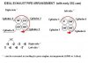
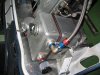
I suppose you have a standard 302 wet sump (if fortunately you have a dry sump SVO block, go the the next step). Modification 1 will be to remove the internal oil pump and to provide a plug in the oil filter hole that is in communication with the pump discharge duct (inlet side). Then you have to provide an oil fitting connector (10 or 12-AN) at the main oil galery (see picture) for oil pressure input (from external pump).
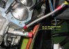
Modification 2 will be to replace both 3/8" screw at the right side of the timing cover by 7/16" studs (see picture). These studs will be in charge to fix the external oil pump support on the block.
b) Timing cover modification
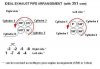
You have to drill both holes for the 7/16" studs (just enlarge existing holes). Then you have to bring it to the workshop to machine the pump support area (to be sure that the oil pump support will be straight). If you have an oil dip stick remove it and put a plug in the hole.
c) Oil tank
Select an oil tank that could be installed as close as possible from your oil pump. Preference is that bottom level is above the oil pump suction point to facilitate oil input with a large hose (16-AN is perfect)
d) dry sump
Select a dry sump with at least 2 suction points (front and side).
e) External oil pump
Select an oil pump according to your dealer local recommendation. The stage number as well the stage size should be in relation with your engine.
Best manufacturers are Barnes, Peterson, Weaver, Gambler, Aviad...
f) Oil pump support
You have to made a strong support to fixe the pump on the block
g) Pulleys
In order to drive the external oil pump, you have to provide:
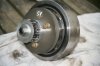
- To remove the existing pulley on the crankshaft
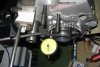
- To fix a new pulley support on the damper (see picture) This support shall be sized in order to have a good alignement with the oil pump pulley as well with the water pump pulley.
- To install a new set of pulley(s) to drive water pump (and alternator if any) on this support
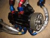
- To install a new Gilmer pulley to drive the oil pump (usually 16 tooth)
- To install a Gilmer pulley on the oil pump shaft (usually 32 tooth to have an initial ratio of 0.5)
- To provide a tooth belt sized accordingly (usual length between 22.5 to 27")
h) Plumbing
You have to provide all oil lines between oil tank, oil pump and dry sump.
Aeroquip style braided lines are recommended. Provide also external oil filter
j) Head cylinder covers
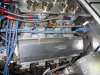
As the dry sump sytem will produce vaccum in the crankcase, you have to remove and to plug the breathers (see picture).
May be I forgot some details but you have here the main lines of the requested modifications to install a dry sump system.
Tomorrow, I will explain to you what are the main advantages of this system ;)
 

Attachments

  • Damper + poulies.jpg
    Damper + poulies.jpg
    58.7 KB · Views: 442
  • Pompe à huile 2.JPG
    Pompe à huile 2.JPG
    94.7 KB · Views: 448
  • Oil tank.jpg
    Oil tank.jpg
    78.2 KB · Views: 420
  • Dérivation huile.JPG
    Dérivation huile.JPG
    77.4 KB · Views: 460
  • No breather.jpg
    No breather.jpg
    98.2 KB · Views: 417
  • Modif bloc 2.jpg
    Modif bloc 2.jpg
    60.3 KB · Views: 434
Last edited:
Back
Top