J. Salmon RCR-40 Build

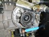
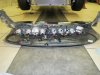
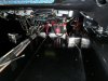
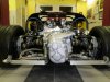
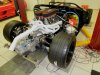
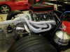
Axle install ends in frustration

If you are familiar with the Ford GT guys, you know that they had issues with the flange retention bolts that hold the splined in-board axle flanges to the transaxle. These are hidden behind the CV joint once it is put together. The factory bolts would break or back out (not sure which) and the axle would pull off the output shaft. This was a source of much frustration.

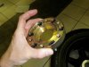
Not wanting any issues, I bought a set of the Accufab bolts from a guy that had sold his GT and never got around to installing them. They are 8mm 12 point bolts with holes for safety wire. I got flange bolts too, but they are too short for these CV joints, so I spent an incredible amount of money on what will ultimately amount to 4 nice bolts. Oh Well.

Torque specs for the Accufab bolts is 15 ft/lbs first pass, then 22 ft/lbs. Since they were drilled, I safety wired them.

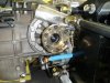
The Porsche CV joints don't actually fit the Ricardo flanges. They are close, but the bolt spacing is not exactly even. So you have two choices to mount to the Ricardo: you can machine the holes a smidge bigger so that the bolts will go in, or you can get an adapter plate made by the Driveshaft Shop (they made the axles too, and there will be more on that in a minute....) I chose the adapter plates.

The adapter gets mounted to the flange: 30 ft pounds first pass, then 57 ft/lbs.

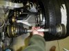
When I went to bolt up the axle I realize, these things are WAY too long. WTH?

The original axles were too long when I got the car. So I sent them back and they shortened them. Then we went to bolt them up and the flanges didn't fit. So I sent them back again, this time to get the adapters and to have the driveshafts shortened yet again to make room for the plate. This second time they went straight to Val's at VIR, where they sat on the floor for who knows how long. I never thought to hold them up when they came back, just made sure I had them. I mean these are clearly not mine, so I guess some poor SLC guy has driveshafts about 6 inches too short.

Looks like they will have to go back, yet again. I am really bummed!
 

Attachments

  • flange bolts.jpg
    flange bolts.jpg
    55.1 KB · Views: 508
  • adapter plate.jpg
    adapter plate.jpg
    32.9 KB · Views: 541
  • adapter mounted.jpg
    adapter mounted.jpg
    51.9 KB · Views: 583
  • too big.jpg
    too big.jpg
    48.9 KB · Views: 536
^^^

That's information I never even knew or heard about before.

So I guess the question is, for us Riccardo owners who don't know wtf we're doing yet,

- are these adapter plates only available from driveshaftshop? (how come I've never heard word 1 of these before? There are a few with Ricardos out there...?)

- I'd imagine the bolts are just regular black oxide grade 12.9 bolts? Do you have the size measurements (thread pitch and length) that one needs?

Thanks
 
The adapters are made by the Drive Shaft Shop. Looks like they mistakenly sent me SLC axles. They have the spec and make the axles for RCR. I should have the correct axles next week.

I like the adapter plate. It is more expensive than simply opening the holes a bit, but it seems more precise. My father's slc must have the open-holed axles, because he does not have adapters. He mentioned that he has had the axle bolts loosen up, but I don't know which ones or any more details. Possibly the bigger holes let the bolts loosen?
 
The use of Bellville washers and locktite should keep them from loosening.
If in doubt, you can always safety wire the bolts.
 
The Drive Shaft shop provides bolts and the spring-style lock washers. I am not sure the dimensions beyond 8mm hex drive. I do have some extras though if any one needs them when I am done.

In the meantime, I have completed the chassis wiring and bundling the mess. I have started building my battery box and pulled the dash back out to wire the switch harness.
 
Completed wiring

This was the area I thought I could not handle, and I am so very glad I did it. I know where everything goes, and it works just like I want it to. I learned: to solder, to crimp, to crimp and solder, how to plan a circuit, how to use a relay, all kinds of stuff that I only knew superficially from physics years ago.

More of the Isis system:
I love the trouble shooting function. I love the flexibility. I immediately found a glitch in my switch harness wiring, which was easy to fix. I wanted to change the way some things work, and that took less than a day.

The base programming includes what is called a "soft start" for the headlights and high beams. It ramps the power up slowly to help extend bulb life. I wired my dash lights off the power to the running lights which don't have this feature, so I had the programming changed. Also, the RF key fob security flashes the running lights once when security turned on, twice for off. This flashed my dash lights, which I didn't like. So I had the programming changed and now it flashes the hazards. I put indicators for the hazards in the dash (turn signal indicators, plus head lights and high beams) and so the green lights flash inside the car too. Nice!

This means I don't have any need for a key. The ECU is disabled with the security on, and the car will not run without the fob. I didn't want to have to fool with a key, and I didn't want a key chain hanging there while driving.

When you power it up, LEDs show which circuits are "hot". When you activiate the corresponding switch, the LED for that channel gets brighter to indicate what is happening. If there is a problem, the mastercell can tell you some of what may be wrong. I know it is not in any way a period look, but I think we are way way past that with this car. The mastercell and rear powercell will ultimately be under covers.

I am working on a spreadsheet which will document where every wire goes.

I mounted the battery in the passenger footwell. I will have a partial encloser that covers the hot side. I also have a custom machined aluminum footrest from Brian Sullivan of pedal maker SRP. If you need something done, he can set you up.

I have aluminum switch panels made. I am going to wait until the car is running and then fit them.

I also got the axles from the Drive Shaft shop, and what do you know they fit!
 

Attachments

  • final dash harness.jpg
    final dash harness.jpg
    48.6 KB · Views: 564
  • mastercell.jpg
    mastercell.jpg
    50.1 KB · Views: 480
  • front powercell.jpg
    front powercell.jpg
    64.2 KB · Views: 565
  • rear powercell.jpg
    rear powercell.jpg
    41.6 KB · Views: 469
  • battery mounted.jpg
    battery mounted.jpg
    42.6 KB · Views: 591
Axles fit.... sorta

I mounted the axles and I am not sure I like them. The angle is really extreme. This picture is at 5.5 inches rear ride height, which will reduce to 4.5 ultimately. Still, you can see the CVs are at a pretty severe angle. You can also see the gold adapter plates. I like them, but I am almost sure they will have to go to help reduce that angle. Going to talk to the driveshaft shop and see what they thing.

Mounted the throttle stop. It came out well. The throttle cable is butter smooth and stops nicely on the pedal box stop, just before the swingset stop. Perfect. At least I understand cable operated stuff.

Also bled the clutch, though no one was around to help me see if its actually working. You can peak in the side of the transaxle to see, but I found it hard to push the pedal and look.
 

Attachments

  • Axles installed.jpg
    Axles installed.jpg
    50.6 KB · Views: 625
  • Throttle stop.jpg
    Throttle stop.jpg
    60.1 KB · Views: 426
  • Throttle stop install.jpg
    Throttle stop install.jpg
    61.8 KB · Views: 519
Re: Axles fit.... sorta

I mounted the axles and I am not sure I like them. The angle is really extreme. This picture is at 5.5 inches rear ride height, which will reduce to 4.5 ultimately. Still, you can see the CVs are at a pretty severe angle. You can also see the gold adapter plates. I like them, but I am almost sure they will have to go to help reduce that angle. Going to talk to the driveshaft shop and see what they thing.

I'm told the off-road guys run the same CVs, with up to 22 degrees of angularity without problems, so the angles you see, if less than that, should be OK.

Possibly different boots might be called for, but those are relatively easy to change when and if there is an issue.

I think the solution set that doesn't involve using adapters is to drill the CVs to the FGT flange size, or remake the FGT bells with the correct bolt circle as the CVs, or adapt a set of the FGT CVs to the axles (in which case you'd have an axle with different CVs on each end. You could also mod up a set of the FGT axles to use 930 CVs on the stub axle side.

The adapter route is clearly the cheapest one. Of the other options, I would look hard at the idea of just using the FGT CVs on the transaxle side.

Let us know what you decide. :thumbsup:
 
I measure it at just under 19 degrees, and that is still 1 inch higher than ride height. I may get to keep the adapter plate yet. I have not safety wired the bolts though, I'll wait until I get approval from those in the business.
 
Headers on. I used copper gaskets from Street and Performance, and locking header bolts. I am modifying the hanger to have a bit of play, more on that later.

12 quarts of oil should do it, with some of that in the filter.

Just out of curiosity, I threw the scales under it. This is dry weight, no body work. I hope to have a wet weight tomorrow.
 

Attachments

  • Oil fill.jpg
    Oil fill.jpg
    58 KB · Views: 573
  • Right header.jpg
    Right header.jpg
    50.1 KB · Views: 486
  • Dry weight no body work.jpg
    Dry weight no body work.jpg
    43.8 KB · Views: 792
Pretty decent corner weights for being right out of the box and (I assume) no attempt at weight jacking to make them perfect. You should be able to get very close.

Like the headers- they must have been made specifically to clear the Ricardo?
 
Will, I did absolutely nothing to balance the corners, just luck so far. It will be spot on when done. Fran made the headers specifically for this car.

Cooling system is tight and holding pressure. Time to fill it... more soon....
 
Sooo close.

Cooling system is full, bled, no leaks. Tranny full. 5 gallons of fuel into tank, fired up the in tank pump and primed the swirl pot, no leaks. Fired up the main pump, no leaks. Fired up the motor....

No go. For some reason, the CAN bus on the FAST XFI is not working. The last time I messed with it (more than a year ago) I had it all working and loaded different parameters for the idle air control. I can see that those parameters are still active. I can see some communication, as the dashboard shows data such as air temp. But the two boxes are not cooperating, and it's not going to run until I figure out why. Unfortunately, no one is around to help until next week, and then we will be out of town. I am sure everything I need is right here in front of me....

Ah well, at least it didn't burst into flames. It does sound mean, even turning over with the starter.
 
Jay,
Dang, nice try, there is always just one little thing that seems to hang you up from hitting a major milestone, like a first start. I had a hold up on my first start on December 4th, and haven't yet over come the problem. My Kennedy Engineered Products bell-housing was drilled in the wrong place for the starter. The bendix drive was hanging up on the flywheel. Took me a while to figure it out.

Good luck and Happy New Year fellow Virginian.
Howard
 
Re: Sooo close.

Ah well, at least it didn't burst into flames.

Visions of the guy from Top Gear going up in flames in the Camparo (sp?) pop into my head.

Congrats on being >< this close.

Oh hey, I just remembered I wanted to ask you what the height of your dad's rear wing was and if it worked well with the mirror location. Or would you/he raise ofr lower the wing for better use of the mirrors?

Thanks
 
Re: Sooo close.

Cooling system is full, bled, no leaks. Tranny full. 5 gallons of fuel into tank, fired up the in tank pump and primed the swirl pot, no leaks. Fired up the main pump, no leaks. Fired up the motor....

No go. For some reason, the CAN bus on the FAST XFI is not working. The last time I messed with it (more than a year ago) I had it all working and loaded different parameters for the idle air control. I can see that those parameters are still active. I can see some communication, as the dashboard shows data such as air temp. But the two boxes are not cooperating, and it's not going to run until I figure out why. Unfortunately, no one is around to help until next week, and then we will be out of town. I am sure everything I need is right here in front of me....

Ah well, at least it didn't burst into flames. It does sound mean, even turning over with the starter.


That wouldn't have happened with a carb ;)

Visions of the guy from Top Gear going up in flames in the Camparo (sp?) pop into my head.

Caparo T1
 
Back
Top