
You are using an out of date browser. It may not display this or other websites correctly.
You should upgrade or use an alternative browser.
You should upgrade or use an alternative browser.
Chuck and Ryan's Carbon Cub Build Blog
- Thread starter CESLAW
- Start date
Auto Pilot, Part II, Kill Switch
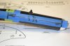
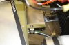
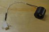
Adding the kill switch was expected to be a real challenge. How does one install a tiny switch inside a long tube and then tighten it once it is positioned? It turned out to be much easier than we expected taking only about 20 minutes.
The location was marked. It is directly below the PTT for the COM, just past where the padded hand grip will end which will keep it out of the way but easily reached. A quarter inch hole was carefully drilled, using a step drill to assured it stayed centered without damaging the trim and PTT wires.
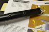
Next a length of stiff TIG welding wire (any stiff thin wire will do) was inserted through the bottom of the tube exiting out the quarter inch hole. The switch was then guided up the welding wire in the opening created by the two wires soldered to the bottom of the switch. With a minimal effort the switch popped right in the hole just as the welding wire was backed out and was easily pulled through so the nut and lock washer could be screwed on. It was tightened with a small wrench without turning the switch. This was a pleasant surprise!
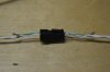
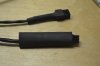
The grommet for the trim / PTT was popped out and the kill switch wire fed through. A separate matching Monel connector was added for the two switch wires and the shield wire. The position of the male and female connectors was reversed from the PTT plug so they would not inadvertently get misconnected
The two conductors are connected, one to ground and the other to GSA04B22 coming from the autopilot harness. The shield was connected to one of the ground wires on the roll servo plug.
Adding the kill switch was expected to be a real challenge. How does one install a tiny switch inside a long tube and then tighten it once it is positioned? It turned out to be much easier than we expected taking only about 20 minutes.
The location was marked. It is directly below the PTT for the COM, just past where the padded hand grip will end which will keep it out of the way but easily reached. A quarter inch hole was carefully drilled, using a step drill to assured it stayed centered without damaging the trim and PTT wires.
Next a length of stiff TIG welding wire (any stiff thin wire will do) was inserted through the bottom of the tube exiting out the quarter inch hole. The switch was then guided up the welding wire in the opening created by the two wires soldered to the bottom of the switch. With a minimal effort the switch popped right in the hole just as the welding wire was backed out and was easily pulled through so the nut and lock washer could be screwed on. It was tightened with a small wrench without turning the switch. This was a pleasant surprise!
The grommet for the trim / PTT was popped out and the kill switch wire fed through. A separate matching Monel connector was added for the two switch wires and the shield wire. The position of the male and female connectors was reversed from the PTT plug so they would not inadvertently get misconnected
The two conductors are connected, one to ground and the other to GSA04B22 coming from the autopilot harness. The shield was connected to one of the ground wires on the roll servo plug.
Attachments
ADS B Out, Part I
The FAA relaxed the standards for experimental aircraft with its announcement of a “performance based standard” for ADS B out in July, 2015, just before Air Adventure. Immediately thereafter Garmin announced the coming GPS 20A which would provide ADS B out with a Garmin ES equipped transponder. This opened the door to affordable ADS-B out. Several other manufacturers have since jumped on the band wagon as well.
The G3X system as packaged by Cub Crafters has all the primary parts needed for the GPS 20A to function including the GDL 39 (for ADS B in) and the GTX 23ES transponder, with the required extended squitter. So before putting the boot cowl in place the time was right to go ahead and get it installed.
Here is a list of parts ordered from Aircraft Spruce:
1. Comant antenna, CI-2480-201 11-05489 @ $573.00
2. Green 22 G hook up wire. 11-07796 @ .27/foot. [6 feet]
3. RG 142, M17/60. MIL-DTL-17 11-00043 @ 3.95/foot [10 feet]
4. 90^ RG 142 TNC connector 11-04450 @ $56.75 [1 each]
5. Straight RG 142 BNC connector 11-01802 @ $3.60 [1 each]
6. GPS 20A 011-03913-00 @ $845.00
7. Garmin Connector kit 011-03914-00 @ $25.00
Only specific antennas will work with the GPS 20A. (The antenna must have an internal amplifier). The Comant antenna is an expensive dual band VHF / GPS, but is what Cub Crafters will be using, so we expect it to work properly. It is specifically identified as an acceptable option in the G3X manual.
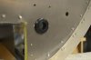
The aluminum turtle deck came pre drilled for the VHF antenna supplied by Cub Crafters. Unfortunately the Comant antenna has a different hole pattern with two antenna feeds: A BNC for the VHF line and a TNC for the GPS line. By placing the VHF BNC in the existing hole, the remaining holes can be drilled and all the pre drilled holes will be covered.
A pattern was made per the supplied dimensions and the forward pattern hole centered over the existing hole.
Once the five additional holes are drilled it looks a bit nasty, but everything will get covered up.
Four 10-32 1 inch long SS bolts were used with small SS fender washers on the bottom side. This is, of course, temporary, since the turtle deck will have to be primed and painted.
ADS-B Out. Part II.
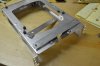
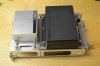
The GPS 20A was mounted on the bottom of the transponder tray directly in front of the GDL-39. Two pieces of aluminum, 6” x ¾” x 1/16” were cut and drilled and installed using counter sunk screws, in the same manner as the GDL-39. Here is the hardware list:
1. AN507C632R8 Countersunk screw (8 each)
2. AN365-632A Nyloc nut (8 each)
3. MS35649-265B Brass nut (4 each)
4. AN936-A6 Lock washer (4 each)
5. AN960-6L Flat washer (4 each)
6. Aluminum, 6 x 1/16 x ¾ inch (2 each)
Note that the way the hardware is used, the two units can be removed by simply unscrewing the nyloc nuts holding the brackets in place without removing the transponder from the tray. Torque seal was placed on the nuts that should not be removed, leaving the remaining clean, so that any would be future service person would be able to see which nuts should be unscrewed to remove the units.
This location for the GPS 20A has several advantages. First, it is a logical location, keeping the two ADS-B units together. Second, it is easily accessible. Third, the LED indicator lights can be seen under the panel. Finally it does not interfere with the pilots legs and is barely noticeable.
The FAA relaxed the standards for experimental aircraft with its announcement of a “performance based standard” for ADS B out in July, 2015, just before Air Adventure. Immediately thereafter Garmin announced the coming GPS 20A which would provide ADS B out with a Garmin ES equipped transponder. This opened the door to affordable ADS-B out. Several other manufacturers have since jumped on the band wagon as well.
The G3X system as packaged by Cub Crafters has all the primary parts needed for the GPS 20A to function including the GDL 39 (for ADS B in) and the GTX 23ES transponder, with the required extended squitter. So before putting the boot cowl in place the time was right to go ahead and get it installed.
Here is a list of parts ordered from Aircraft Spruce:
1. Comant antenna, CI-2480-201 11-05489 @ $573.00
2. Green 22 G hook up wire. 11-07796 @ .27/foot. [6 feet]
3. RG 142, M17/60. MIL-DTL-17 11-00043 @ 3.95/foot [10 feet]
4. 90^ RG 142 TNC connector 11-04450 @ $56.75 [1 each]
5. Straight RG 142 BNC connector 11-01802 @ $3.60 [1 each]
6. GPS 20A 011-03913-00 @ $845.00
7. Garmin Connector kit 011-03914-00 @ $25.00
Only specific antennas will work with the GPS 20A. (The antenna must have an internal amplifier). The Comant antenna is an expensive dual band VHF / GPS, but is what Cub Crafters will be using, so we expect it to work properly. It is specifically identified as an acceptable option in the G3X manual.
The aluminum turtle deck came pre drilled for the VHF antenna supplied by Cub Crafters. Unfortunately the Comant antenna has a different hole pattern with two antenna feeds: A BNC for the VHF line and a TNC for the GPS line. By placing the VHF BNC in the existing hole, the remaining holes can be drilled and all the pre drilled holes will be covered.
A pattern was made per the supplied dimensions and the forward pattern hole centered over the existing hole.
Once the five additional holes are drilled it looks a bit nasty, but everything will get covered up.
Four 10-32 1 inch long SS bolts were used with small SS fender washers on the bottom side. This is, of course, temporary, since the turtle deck will have to be primed and painted.
ADS-B Out. Part II.
The GPS 20A was mounted on the bottom of the transponder tray directly in front of the GDL-39. Two pieces of aluminum, 6” x ¾” x 1/16” were cut and drilled and installed using counter sunk screws, in the same manner as the GDL-39. Here is the hardware list:
1. AN507C632R8 Countersunk screw (8 each)
2. AN365-632A Nyloc nut (8 each)
3. MS35649-265B Brass nut (4 each)
4. AN936-A6 Lock washer (4 each)
5. AN960-6L Flat washer (4 each)
6. Aluminum, 6 x 1/16 x ¾ inch (2 each)
Note that the way the hardware is used, the two units can be removed by simply unscrewing the nyloc nuts holding the brackets in place without removing the transponder from the tray. Torque seal was placed on the nuts that should not be removed, leaving the remaining clean, so that any would be future service person would be able to see which nuts should be unscrewed to remove the units.
This location for the GPS 20A has several advantages. First, it is a logical location, keeping the two ADS-B units together. Second, it is easily accessible. Third, the LED indicator lights can be seen under the panel. Finally it does not interfere with the pilots legs and is barely noticeable.
Attachments
ADS-B Out, Part III.
The RG-142 antenna cable for the GPS-20A was routed on the left side, opposite the VHF cable, to minimize the risk of interference. The cable is ten feet long. The power connection was routed to the avionics bus with an inline 3 amp fuse.
Although both the GDL-39 and the GPS 20A have in line fuses, we opted to wire them to a circuit breaker on the Avionics bus as well. Since we deleted the autopilot control head and replaced it with the two steam gauges, the circuit breaker marked GMC was not being used. It came with a 2 amp breaker, which we replaced with a 5 amp breaker. This gives us the option of manually disabling the two ADS B units by simply pulling the breaker. The “GMC” will be relabeled “ADSB.”
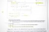
The wire harness is a simple affair, as detailed in the G3X manual. The RS 232 Channel was used. Figure 23-2.3 from the G3X manual.
The plug pins were soldered. Silicone self-adhesive tape was wrapped around the crimp point. I had not used this tape before; it is pretty neat stuff.
A #5 cushioned clamp was used to secure the wire to the side of the transponder tray.
That green LED was a reassuring sight when it was powered up for the first time!
The RG-142 antenna cable for the GPS-20A was routed on the left side, opposite the VHF cable, to minimize the risk of interference. The cable is ten feet long. The power connection was routed to the avionics bus with an inline 3 amp fuse.
Although both the GDL-39 and the GPS 20A have in line fuses, we opted to wire them to a circuit breaker on the Avionics bus as well. Since we deleted the autopilot control head and replaced it with the two steam gauges, the circuit breaker marked GMC was not being used. It came with a 2 amp breaker, which we replaced with a 5 amp breaker. This gives us the option of manually disabling the two ADS B units by simply pulling the breaker. The “GMC” will be relabeled “ADSB.”
The wire harness is a simple affair, as detailed in the G3X manual. The RS 232 Channel was used. Figure 23-2.3 from the G3X manual.
The plug pins were soldered. Silicone self-adhesive tape was wrapped around the crimp point. I had not used this tape before; it is pretty neat stuff.
A #5 cushioned clamp was used to secure the wire to the side of the transponder tray.
That green LED was a reassuring sight when it was powered up for the first time!
Attachments
Firewall, Gascolator
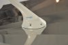
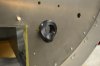
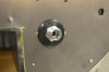
Something about putting a square peg into a round hole; that’s what was going through my mind as I struggled to insert a grommet with an inside diameter the same as the hole it was supposed to go into. A call to Mitch confirmed that this was indeed the right grommet, I just needed to try harder.
With some effort it did indeed go in.
Just for fun, the fuel line fitting was pushed in place. Really snug. But now the method behind the madness became clear: the purpose of the oversized grommet is to provide a very tight seal around the fuel line fitting. Sometimes knowing where you are supposed to end up makes it a lot easier to figure out how to get there.
Attachments
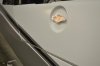
Control stick handle
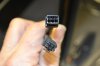
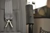
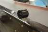
We ordered the optional padded control stick covers. They are inexpensive (by Cub Crafter’s standards) and come in pairs: not because you need two but because you will likely destroy the first one when putting it on. So here is our little trick to make installation easy.
A strip of plastic was cut from a zip lock sandwich bag about an inch wide and as long as possible. This was placed over the PTT switch extending both above and below where the padded cover would end up.
A bit of dish soap was rubbed on the control stick.
The padded handle was slid into place. It goes on easily until you hit the PTT switch. At that point the plastic from the sandwich bag will help guide it over until the hole is centered. Once in place pull the plastic sandwich bag material from the top and bottom. It should rip about where the PTT switch is located and come out in two sections, top and bottom.
If I had done this the first time I would now have an extra padded handle without a rip.
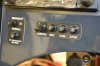
The PTT switch is barely visible. The lower switch is the autopilot override.
We ordered the optional padded control stick covers. They are inexpensive (by Cub Crafter’s standards) and come in pairs: not because you need two but because you will likely destroy the first one when putting it on. So here is our little trick to make installation easy.
A strip of plastic was cut from a zip lock sandwich bag about an inch wide and as long as possible. This was placed over the PTT switch extending both above and below where the padded cover would end up.
A bit of dish soap was rubbed on the control stick.
The padded handle was slid into place. It goes on easily until you hit the PTT switch. At that point the plastic from the sandwich bag will help guide it over until the hole is centered. Once in place pull the plastic sandwich bag material from the top and bottom. It should rip about where the PTT switch is located and come out in two sections, top and bottom.
If I had done this the first time I would now have an extra padded handle without a rip.
The PTT switch is barely visible. The lower switch is the autopilot override.
Attachments
Boot Cowl, Anti Chafe
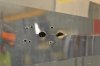
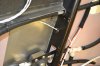
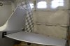
There was this piece of plastic, 12” x 3”, part number SC71010-001, described as “anti-chafe”. It was referenced in a drawing, but frankly its function did not jump out at me. After the boot cowl was set in place it made sense: it protects the switches.
A pattern was made to assure the minimal amount of plastic was cut away to clear the two frame tubes. Less obvious, however, is the notch that needs to be cut to clear the rib on the underside of the top of the boot cowl. It is off center about a half inch. We cut a half inch wide notch, off center a half inch, to make sure there would be no clearance issues.
Installing it with the boot cowl in place was a challenge. Once the location of the cuts was confirmed the cowl could have been moved forward which would have simplified the job.
That pattern also came in handy when trimming the black vinyl to clear the tubes and boot cowl rib. The width of the vinyl was trimmed to match the depth of the anti-chafe strip: approximately three inches
I was amazed at how everything lined up. The openings around the frame tubes are exactly centered in the openings. Kudo’s to Cub Crafters for the precision of the design and manufacture of these parts, especially on something with as many large and small parts as the boot cowl.
Wiring, Throttle PTT
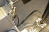
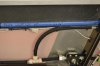
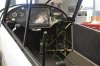
We added a PTT switch to the throttle knob. (Ryan made a batch of the knobs a while back. We decided to use the Delrin knobs). Two strand shielded wire (Aircraft Spruce 11-05650) was connected to the PTT connection under the seat. The wire was routed up the left side with the wire harness to the area behind the throttle controls. A grommet was placed where the wire passed through the frame and it was nylon tied in place.
A two pin Monel plug was used so that the wire could be easily connected or disconnected when the interior panel was set in place or removed. The wire was nylon wire tied in place so that the plug was 10.5” aft of the forward vertical brace with the plug facing forward. This dimension is intended to assure that the wire attached to the throttle lever will not interfere with the throttle when moved. The plug needs to be secure to make sure the wires do not slip into the throttle mechanism.
The PTT switch (Aircraft Spruce, P/N 11-03909) was wired with 22 G wire (we used the two conductors from the same shielded cable, without the shield. The shield made it too stiff). A matching Monel connector was connected to the opposite end of the 11” wire.
A hole was drilled about an eighth inch from the aft edge of the throttle lever, carefully locating it so that it would be just above the opening in the carbon fiber panel when the throttle is at its limits of travel. A thin piece of wire was used to hold it in place. A short length of heat shrink was used to cover the wire.
Spiral wrap, 3/16”, Cub Crafter RM1004-002, was used to cover the wire from the plug to just where the lever extends above the carbon fiber panel.
The rear passenger will have a matching throttle without the PTT.
Ryan plans to mill additional throttle knobs in the near future, both with and without the hole for the PTT button if anyone is interested.
Attachments
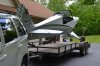
Two years
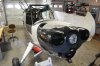
Two years ago the 18 foot long box landed in my garage.
As of now the Cub is just about ready to go to the hanger for final assembly. Ninety percent done, fifty percent to go.
At this point about 900 hours have been invested in actual build time.
Two years ago the 18 foot long box landed in my garage.
As of now the Cub is just about ready to go to the hanger for final assembly. Ninety percent done, fifty percent to go.
At this point about 900 hours have been invested in actual build time.
Attachments
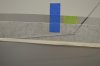
Stripes
Here is how we applied the stripes. Although this is an airplane post, I used the same general technique on the GT.
1. Fill a quart spray bottle with distilled water. Add a few drops of dish soap and a couple table spoons of denatured alcohol.
2. Trim the top edge of the top stripe while the backing paper is in place exactly even with the stripe.
3. Wipe down the fuselage where the stripe will go with denatured alcohol to make sure it is absolutely clean.
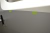
4. Apply ¾ pieces of masking tape (about an inch long or so) even with the bottom of the adjacent paint line at about 18” intervals. This defines the spacing of the stripe.
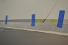
5. Tape the stripe with green or blue masking tape, with the paper backing in place, on the top edge only, exactly even with the bottom of the masking tape spacers. This will pinpoint the location of the stripe. Put these tapes about a foot apart to make sure the paper backing with the stripe stays put.
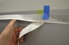
6 Now gently lift the stripe with the backing still intact from the bottom edge and begin removing the paper packing from the adhesive side of the stripe. While holding it up after the backing is removed, spray the area where it will be applied with the water solution. Try not to get the water on the paper being removed because it can dissolve and leave a residue on the sticky surface of the tape. Now gently set the adhesive side of the stripe in place. Do NOT apply pressure just yet.
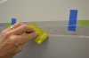
7. Work your way the length of the tape until you get to the opposite end. Now use a squeegee or rag on the backing to push the stripe in place and remove the bubbles, if any.
8. With the stripe stuck in place, spray the paper backing with more water solution. By this time the masking tape spacers and the outside backing will be getting pretty soggy and will come off easily.
9. With the stripe in place and the backing removed, gently wipe the stripe with a micro fiber towel dampened with the water solution. Don’t worry about small bubbles. They will disappear over time, especially once it gets out in the sun.
10. We pre trimmed the areas around the hinges and applied each section separately.
11. The lower stripe is done in the same fashion, but because the spacing tapers from about four inches at the rear to ¾ at the front, fewer spacing tapes are needed. Just measure the length, divide it in to roughly equal quadrants, than place spacing tapes that taper consistently front to rear. At the front make sure to keep the distance at 3/4" to match the spacing of the top tape.
Here is how we applied the stripes. Although this is an airplane post, I used the same general technique on the GT.
1. Fill a quart spray bottle with distilled water. Add a few drops of dish soap and a couple table spoons of denatured alcohol.
2. Trim the top edge of the top stripe while the backing paper is in place exactly even with the stripe.
3. Wipe down the fuselage where the stripe will go with denatured alcohol to make sure it is absolutely clean.
4. Apply ¾ pieces of masking tape (about an inch long or so) even with the bottom of the adjacent paint line at about 18” intervals. This defines the spacing of the stripe.
5. Tape the stripe with green or blue masking tape, with the paper backing in place, on the top edge only, exactly even with the bottom of the masking tape spacers. This will pinpoint the location of the stripe. Put these tapes about a foot apart to make sure the paper backing with the stripe stays put.
6 Now gently lift the stripe with the backing still intact from the bottom edge and begin removing the paper packing from the adhesive side of the stripe. While holding it up after the backing is removed, spray the area where it will be applied with the water solution. Try not to get the water on the paper being removed because it can dissolve and leave a residue on the sticky surface of the tape. Now gently set the adhesive side of the stripe in place. Do NOT apply pressure just yet.
7. Work your way the length of the tape until you get to the opposite end. Now use a squeegee or rag on the backing to push the stripe in place and remove the bubbles, if any.
8. With the stripe stuck in place, spray the paper backing with more water solution. By this time the masking tape spacers and the outside backing will be getting pretty soggy and will come off easily.
9. With the stripe in place and the backing removed, gently wipe the stripe with a micro fiber towel dampened with the water solution. Don’t worry about small bubbles. They will disappear over time, especially once it gets out in the sun.
10. We pre trimmed the areas around the hinges and applied each section separately.
11. The lower stripe is done in the same fashion, but because the spacing tapers from about four inches at the rear to ¾ at the front, fewer spacing tapes are needed. Just measure the length, divide it in to roughly equal quadrants, than place spacing tapes that taper consistently front to rear. At the front make sure to keep the distance at 3/4" to match the spacing of the top tape.
Attachments
Time for the D Type?? ")
Looks great Chuck:thumbsup:
This video is for you....turn up the speakers:shocked:
http://youtu.be/xSl_632bOH4
This video is for you....turn up the speakers:shocked:
http://youtu.be/xSl_632bOH4
Similar threads
- Replies
- 17
- Views
- 14K
- Replies
- 16
- Views
- 6K