Very, very nice ! What's the expected all-up weight?
Around 950 lbs. dry. Gross around 1800, unless I choose to keep it light sport, which would limit it to 1320 gross

Very, very nice ! What's the expected all-up weight?
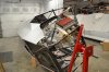
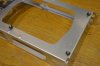
Fuselage painted
[
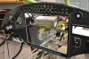
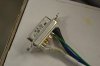
The engine and avionics will be here in the next few days. The timing could not be better.
Not worrying me, its your plane, but once you get comfortable with flying it try covering the panel and fly it blind- no instruments ( with someone flight capable in the back seat and away from controlled airspace), couple of hours of that will open up a whole new world.
Having built a couple of Heathkit kits - I thought they were very good but also tedious... This is an amazing build and your patience and attention to detail are unparalleled in my opinion..
")