

You are using an out of date browser. It may not display this or other websites correctly.
You should upgrade or use an alternative browser.
You should upgrade or use an alternative browser.
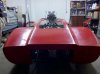
blown mkiv
- Thread starter roots
- Start date
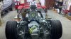
Whoa, nice, that intake will see some clean air! i see a ricardo, did you change out the bolts/washer that secure the axle internally?
If you go on the ford gt blogs they are known to shear with high hp. I think you'll have a few horse in that setup!
It wasnt fun shearing mine, the half shaft becomes a rotating weapon. plus youre found on road dead. It was the best $160 i spent...
If you go on the ford gt blogs they are known to shear with high hp. I think you'll have a few horse in that setup!
It wasnt fun shearing mine, the half shaft becomes a rotating weapon. plus youre found on road dead. It was the best $160 i spent...
Attachments
Howard Jones
Supporter
The basic plan is to:
1. Place the header tank as high in the car as possible. This will usually be up on the firewall in the engine room to the right or left of the the engine. Leaft clearance of a radiator cap.
2. I have seen many people use a aftermarket header tank such as a Moroso. See Summit racing or many other catalogs. You can also have one made to your requirements of modifiy a after market tank.
3. The car will have several places that are the highest points in the respective part such as the engine, radiator, and if you have one the heater core. If you leave it to the general flow of coolent through these parts to bleed out air it becomes a potential problem.
Many, including myself have installed a self bleeding system in their cars to allow a alternative path for the air to return to the header tank from these places. I have used the bleed bungs on the top of the radiator to install AN-4 fittings and then run a 1/4" line back to the header tank. I have also done the same at the back of the intake manifold and
at the temp sender port of the manifold .This provides a three point bleed system off the top of the engine to return air to the header tank.
I don't have a heater in my car so I am not sure that it would be required , but if I still had bleed problems I would do something similar there also.
So you will need a few bungs on your header tank to use for bleed lines. See my SLC thread for pictures.
My GT40 NEVER has a air in the water problem now.
4. The expansion line, usually a AN-8, goes from the high pressure side (hot out to radiator) of the coolent system to the bottom of the header tank. Usually a bung is welded onto the coolent tubing and a fitting in installed at each end of the hose. One on the header tank and one on the main coolent tubing.
I have seen cars with the expansion line on the low pressure side and it seams to work there also. I just think it should be on the high (hot) side. Others will correct this I need be.
Thats it. good luck.
By the way your blower must be a first. Geese!!!!!!!!!!!!!!!! got enough motor there son? Said in good fun.
Last edited:
DTO what Howard said.
went with a air bleed line from the top of the radiator to the expansion tank (selfbuilt) and also with an air bleed from the back of the intake to the ep tank.
Expansion line is coming from the suction side of the waterpump in my case.
Seems to be working as well. I run a heate, but have no bleed lines for that.
expansion line is 16mm inner diameter. bleed lines are AN3.
One thing i would change is that i would have the bleed lines also coming into the ep-tank in the lower third. This way they would always be suspended in water and when the engine cools down, the created vacuum would suck in water and not air and thus the system don´t need to bleed itself again. Never had an issue with air in the system, just filled it up via the ep-tank and refilled after the first runs. I
I also have an overflow bottle. I overfilled the system once and it priged into the overflow, but after cooling down the vacuum sucked it back in. So make shure your header tank has a correct header cap bung welded in which does allow that.
check out this 3 posts
http://www.gt40s.com/forum/gt40-build-logs/24525-toms-rcr-40-trackracer-18.html#post281962
http://www.gt40s.com/forum/gt40-build-logs/24525-toms-rcr-40-trackracer-18.html#post283707
http://www.gt40s.com/forum/gt40-build-logs/24525-toms-rcr-40-trackracer-24.html#post316788
TOM


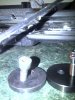
Thanks for your emails keep sending them .cam i will have to check with fran on washer and bolt.if i do not have how do you install them
thanks wayne
Wayne, Simple if you have the half shafts off. Remove the old 10mm allen bolts and washer. Throw in the trash. Locktite new ARP's on there. Took a little heat to loosen up the Ricardo locktite. The torque spec is pretty low, I want to say 40ftlbs.
The accufab kit come with drilled axle bolts but hey were too short to use with the driveshaft shop axles. Link below. Might be able to find it cheaper w/o the drilled bolts? Roots, sorry to get off topic, just saw the blower and thought you'll be laying down some torque!
Ford GT Rear Axle Bolt Kit from Accufab 05-06
Torque is 28-30ft-lbs.
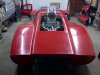
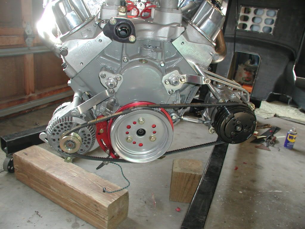
Hi new question motor is 351w (small block ford) i am trying to mount alternator and air conditioner so i can hook up cooling system.i have alt and bracket that will match the last grove and water pump pulley and would have to run water pump and alt together but will air comp be to long to use other groove left behind water pump groove.i could buy electric water pump but i do not trust electric stuff.any thoughts please.
Attachments
Seymour Snerd
Lifetime Supporter
Hi new question motor is 351w (small block ford) i am trying to mount alternator and air conditioner so i can hook up cooling system.i have alt and bracket that will match the last grove and water pump pulley and would have to run water pump and alt together but will air comp be to long to use other groove left behind water pump groove.i could buy electric water pump but i do not trust electric stuff.any thoughts please.
Not sure I follow you, but here's what I think you are saying: You have a three-groove crank pulley (or pair of pulleys) and have an alternator bracket that aliigns the alternator pulley with the front groove of the crank pulley, as does the water pump pulley.
Then you asked "will air comp be to long to use other groove left behind water pump groove" and that's where you lost me. By "last grove" do you mean the front groove on the crankshaft pulley? Since there is only one groove on the water pump pulley, I assume by the groove "left behind" you mean the middle groove on the crank. So I guess you're asking if you can run the compressor on the middle groove of the crank with a reasonable belt length. The answer is yes, as long as you don't put the compressor a long way from the crank.
Thanks for email awatkins yes that is what i am asking .i do not have air comp yet ,the alternator is very close to the head on right side of car if i mount the air comp on the left side of car and the air comp is longer it will not fit. Are their air comp close to the size of alternator?
Seymour Snerd
Lifetime Supporter
Thanks for email awatkins yes that is what i am asking .i do not have air comp yet ,the alternator is very close to the head on right side of car if i mount the air comp on the left side of car and the air comp is longer it will not fit. Are their air comp close to the size of alternator?
Both alternators and compressors come in many different sizes so it's an impossible question to answer. Also the compressor needs to "match" the other parts of the system (condensor and evaporator) to operate at peak efficiency. IF you can, it saves a lot of time to use original brackets for compressor and alternator, and they're usually not terribly expensive. But I don't know if that would fit your car; obviously for a 351 they would have been designed for the front end of a sedan or truck. If I were you I'd probably be calling Fran right about now.
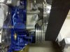
Wayne,
You might coonsider using a custom mount for your alternator and your A/C. I did away with my water pump and went with an electric unit. I get temps in the 150s with it just idlying. On the street I don't know yet as I am working out some bugs in the car. Here are the mounts I made and it works well. They are made to fit close to the engine and away from the frame members. The mesurements have to be done with the engine in the car, as clearances in these cars are close. Evrything is tucked away and there are no bind issues. The reason they are not made the same is that I have water lines and fuel lines comming down the alternator side of the engine and there was no space left. If you elect to keep the water pump it is just a matter of getting a belt to fit. Just remember that when you wind that motor up you will be cavitating the water with those high rpms. no such thing with an electric. Controlling things is a breeze and just a matter of hookng up the right wiring that you want. It can be electronic or manual with a thermostat. A thermostatic bypass is easily done and there are some great examples here in the forum. A second feature is tha you can move the engine a little more forward. Connecting the return lines can be a solid piping or hoses to a manifold. Its like putting a puzzle together!!
Bill
Seymour Snerd
Lifetime Supporter
.IF you look at the side of the engine is the back of the compressor Past the face of the head?
If you can figure out which compressor you are going to use, and it's a Sanden, you can find dimensioned drawings of their compressors on their web site.
Similar threads
- Replies
- 45
- Views
- 3K