CANAMSA - SA stratch build

Thanks for the comments Guys

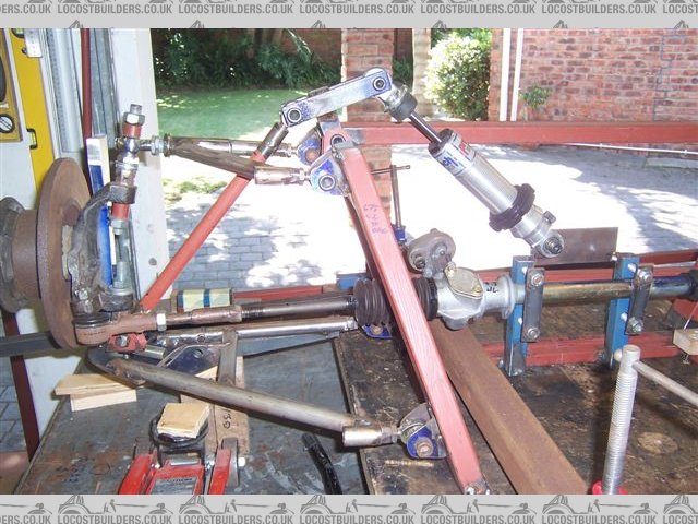
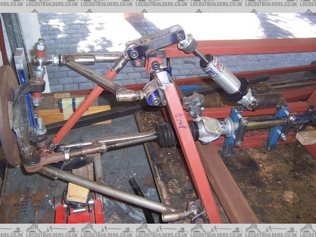
Front uprights - Although I did spend some time messing about with the detail in the interest of just getting on with it I am going to, at least initially, use standard (non optimal) Cortina uprights, with adaptors to the rod ends. Eventually I might make some improved geometry ones.

Cheers

Fred W B
 
Hi Fred, hope your doing well.

How are things comming along? Hope your chassis is comming along OK.

I have started building again (on a GD Euro Cobra). Which will be ran with the LOLA keycord just to remind me to build a new one someday.

Grtz Thomas
 
Hi Thomas

Good to hear from you again, and that you have another intersting car project on the go.

As for my progress on the chassis, although I have now got the rearmost section of the chassis and rear suspension pretty much laid out none of it is yet up to the final, real part stage. Although at least I got a batch of suspension attachment brackets made.

Have spent much time deliberating over material thicknesses, and tube sizes and things like how much wheel travel and ground clearance is needed. I tend to want to over engineer everything and am trying hard to keep the details light and simple.

Also done quite a lot of fiddling with a prototype gear linkage.

Some photos, note that this is still mock up work, chassis braces fitted on one side only and the wishbones shown are very rough representations in small tubes.


October%20001.jpg


October%20002.jpg

November%2004.jpg


November%2001.jpg


November%20002.jpg


November%20007.jpg


November%2009.jpg
 
I've also spent quite a bit of time mocking up the front suspension, and I'm starting to think about trying to make an inboard mounting for the coilover work.

The major issue it will solve is that, with the coilover in the conventional position, I can't use all of the damper travel of the units I already have. Plus positioning the coilover so it can be mounted at something like a sensible angle, and still clear the top wishbone was problematic.

Another advantage of the inboard setup is that the pushrod length can easily be altered, to give a wide range of ride height adjustment. This mock-up bell crank has ratios that give a one to one relationship between wheel travel and coilover displacement.

I am aware that I will have to engineer a decent pivot detail in the rocker arms, unless I can find something off the shelf. Anyone know what bearings some manufacturers with a successful detail use?

The wishbone attachment brackets will be made wide enough so I can adjust the castor from 5 to 10 deg by shimming the inner mounts. I need to keep the wheel in the centre of the wheelarch so both the top and bottom attachments need to have this detail.
sad.gif


Cheers

Fred W B


FS%20001.jpg


FS%20002.jpg
 
Hi Fred looking like progress to me!

For simplicity, why not pyramid/triangel the upper front wishbone and mount it directory to the coilover, this means far less moving parts les inspring weight and more room for Brakes, it also means an very strong wishbone which is good in case of an crash..... (Believe me I know)

Look at the GD design it shows exactly what I mean.

Same Goes for the rear, btw but there GD uses the power wishbone to attach the coil and clear the exhausts.

It indeed deels good to be building again dunn'it?

Grtz Thomas
 
Fred
Just a comment from looking at your suspension pics.
Are there any Mazda MX5 wrecks that you could use the front suspension bits from, I lucked on a complete set and the advantage apart from better off set`s,
You end up with modern components. By putting the shocks inboard you can also control the shock angle totally. You can see that my shocks appear almost vertical because I have calculated (read guessed) the direct angle of suspension rod input so that the shock is working at the optimum angle. The other big advantage is I think that ride height is a simple twist of the suspension rod.
My thoughts only.
Love those brackets.Russell
 

Attachments

  • DSCF2553.jpg
    DSCF2553.jpg
    247.8 KB · Views: 749
  • DSCF2554.jpg
    DSCF2554.jpg
    218.1 KB · Views: 711
  • DSCF2555.jpg
    DSCF2555.jpg
    242.2 KB · Views: 683
Thanks for the comments guys. I really want to button down this stuff and start making real parts/chassis.

Thomas, I have seen the GD setup. It does mean taking all of the wheel bump loads throught the top upright joint, and I have been planning to do that through the bottom joint. Also the top rocker arm bearings have to be pretty fancy to also take the fore and aft loads.

Russell, while I appreciate the sentiment, MX 5"s are not common over here. I see that it looks like your steering rack is positioned directly between the steering arm attachment points on the uprights. Based on some reading I have positioned the steering rack 50 mm behind these points, in order to get some (enough?) Ackerman affect. Did you consider this at all? Anyone else care to comment?. Putting my steering rack further forward would help with some packaging issues.

Cheers

Fred W B
 
Last edited:
Fred
I thought most of the Ackerman was built into the position of the steering arms and if you have too much bias on the rack position, you will end up with excessive bump steer.
I have also attached the Del Oroto plates if that helps.
Cheers
Russell
 

Attachments

  • Scan0002.jpg
    Scan0002.jpg
    43.1 KB · Views: 687
Thanks for the comments guys. I really want to button down this stuff and start making real parts/chassis.

Based on some reading I have positioned the steering rack 50 mm behind these points, in order to get some (enough?) Ackerman affect. Did you consider this at all? Anyone else care to comment?. Putting my steering rack further forward would help with some packaging issues.

Cheers

Fred W B

Hi Fred, I did extensive research and subsequent mods on my car recently due to an ackerman design issue it had. It seemed to me after exhaustive research that the rule of thumb for a typical track to wheelbase ratio is

a) for a front rack, a 75 degree included angle between the rack trackrod and a line through that runs through the trackrod end and kingpin axis at rack height (this is looking down on the car), or

b) for a rear rack, a 105 dgree included angle.

c) assuming rack width and height are set-up right(!).

You can move the rack fore and aft as long as you observe that included angle rule, but obviously none of it holds if the rack is not at the right height and/or trackrod length is off.

Cheers, Andrew
 
Andrew
I think I have got that mentally??? could you draw a simple line drawing to confirm what I am visualizing.
That angle would change obviously as you moved the rack back and forth?
I will go and measure what I think you have described.
Cheers
 
Andrew
Couldn't resist checking now..its a lovely night, warm as, 9.32pm.
With the wheels set straight ahead, my angle is 78 / 79deg and I have at least 15mm of rearward adjustment available if needed. Would too much angle from moving the rack rearwards not induce bump steer? probably not so much of an issue with very short suspension travels.
Cheers
Russell
 
Andrew
I think I have got that mentally??? could you draw a simple line drawing to confirm what I am visualizing.
That angle would change obviously as you moved the rack back and forth?
I will go and measure what I think you have described.
Cheers

Hi Russell, yeah you are right. I found Allan Staniforth's book "Competition Car Suspension - A Practical Handbook" really useful. There is a whole section on there about ackerman. Two diagrams from that bit is attached:

andrewrobertson-albums-mclaren-m1b-replica-build-photos-picture1483-ackerman-2.jpg


andrewrobertson-albums-mclaren-m1b-replica-build-photos-picture1482-ackerman.jpg


The new bit for me was that the traditional approach of lines to centre of rear axle needs to change whenever the rack is not mounted straight between the track rod ends. In the second diagram you can see that if you move the rack forward, you have to put a more aggressive angle on the steering arms to preserve the included angle.

Cheers, Andrew
 
Thanks for further comments guys.

Russell, my understanding is that bump steer is only concerned with the positions of the tie rod ends in front view, as the outer one moves in an arc with the suspension movement up and down. A therotical starting point is putting the inner tie rod joint on a line that joins the upper and lower inner wishbone pivots, and at a height that is proportional to the position of the outer tie rod attachment point from the upper and lower outer pivot points at the upright. I did this and then adjusted the rack up and down in 5 mm steps untill I found a position with almost exactly zero bump steer.

And thanks for the flange drawing, that will be helpfull when I get to that stage

Andrew, I also went and measured my angle and it looks to be just about (get this) 73 degrees. So moving the rack slightly foward will get me to 75 degrees. Thanks for sharing the benefit of your research.

Cheers

Fred W B
 
Last edited:
When moving rack fwd be aware of this possibility on full lock and fit steering lock stops preferably on the upright/wishbone interface to prevent.
 

Attachments

  • user19385_pic1482_1428572743.jpg
    user19385_pic1482_1428572743.jpg
    78.3 KB · Views: 644
Thanks for further comments guys.

Andrew, I also went and measured my angle and it looks to be just about (get this) 73 degrees. So moving the rack slightly foward will get me to 75 degrees. Thanks for sharing the benefit of your research.

Cheers

Fred W B

Hi Fred, seems like you are really close already. The thing that comes through from several diferent writers is to get it in the right ball park and forget about that last 10-20% of perfection on the basis that the inside wheel is very lightly loaded in turns at speed anyway. I think geometry for minimisation of bumpsteer is probably more important if ackerman is in the right ball-park.

Cheers, Andrew
 
Hi

Not much of an update.

It seems that I've got a bit bogged down in trying to finalize too many details all at once, suspension, radiator size/placement, roll bar shape/height, hingeing the tail and possibly the most problematic being the position of the fuel tank/s. Im not keen to put them alongside the driver/passenger.

I've now decided against the fuel tank position shown in the pictures, it's right on the perimeter of the car so very close to an accident. Also very close to the engine/exhausts. Now planning to put all the fuel inside the chassis, behind the seat bulkhead. Need to decide how much fuel capacity is required, is 70 L enough?

Hoping to start welding up the real chassis pretty soon. Some of the chassis members are not represented in these pictures.

Cheers

Fred W B


roll%20bar%2002.jpg


fuel%20tank%20p2.jpg


fuel%20tank%20p1.jpg
 

Ian Anderson

Lifetime Supporter
Fred
Fuel capacity
My GT40 has twin tanks of About 27 litres each

On my fuel injected 3.9 Rover engine I get between about 6mpg and 8mpg on track (track days not racing)
And best ever on a slow drive back from LE Mans in a 50mph queue got 32mpg

The engine is fiairly highly tuned at 256hp

Hope that gives some indication as to how many laps / minutes your car will return for a set fuel capacity

Ian
 
Hi Fred, Things are coming along nicely. I wouldn't have my tank in that spot either but more for weight distribution. I would tend to go for long tanks running from the front of the engine forward. Just looking at the side pods, they seem quite wide so you could insulate them from side impact with a layer of dense foam. If you use 16L/100km (17mpg) your 70L will give you a 430km range, not sure about SA but that's plenty in NZ. BTW your suspension set up looks nice.

Cheers Leon.
 
Back
Top