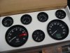
Gauges, Installation and Wiring
This post probably won’t make much sense unless you have a set of Speed Hut gauges sitting in front of you waiting to be installed. Sorry.
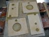
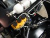
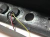
Fuel Gauges. The fuel senders use inductance rather than floats. This eliminates mechanical problems and simplifies installation. The senders use the same size cover plate as the Classic gauges, so retrofitting the senders would not be an issue. The supplied sender wire is shielded with two conductors, one of which is a ground. (The shield is not grounded). We cut off the supplied wire from the plug that connects to the gauge, leaving about four inches to work with, grounded the black wire at the dash, and connected the white wire to the existing sender wire. At the tank, the existing sending wire and ground were connected to the new sending unit. Note that the inductive sender requires a 12 volt power source. Rather than run another wire from the dashboard, the MSD ignition wire (switched with the ignition) was tapped, which greatly simplified the wiring.
Temperature and Pressure Gauges. The Speed Hut gauges come with the electrical senders for water temperature, oil temperature, and oil pressure. The temperature gauges use two conductors (sender and ground) with a non-grounded shield. Since we had previously wired the car with a single sending unit wire, we simply cut the supplied wire about four inched from the plug that connects to the gauge, grounded the black wire at the dash, and connected the white wire to the existing sender wire. The supplied wire would not be long enough to reach from the dash to the engine regardless. We will use the supplied wire with the shield in the engine compartment and then add the splice where it won’t be seen.
The oil pressure gauge uses three connectors, one of which provides a low voltage source to the sender. The original single sender wire used with the Classic gauge was not used. A splice will be needed to reach the engine compartment.
A call to Speed Hut confirmed that shielding is not required for the temperature and oil pressure sender wires, so splicing in an extension is not an issue. Nonetheless the shielded plug ends will be used in the engine compartment.
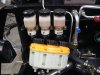
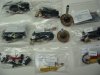
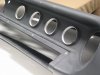
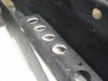
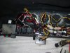
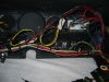
Wiring. The Classic gauges used screw terminals for most connections. When the dash was originally wired, all the gauge wires were carefully laid out and wire tied neatly directly behind the gauges. The Speed Hut gauges use plugs to which all the wires are connected with pre cut harnesses. The old wire harness was no longer necessary and most of the old wiring was simply removed and replaced, connecting the existing sensor wiring to the new Speed Hut wires.
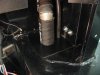
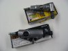
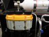
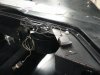
The Speed Hut gauges use a small ‘inverter’ which powers the lights and includes a rheostat to control the brightness of the lights. This was held in place with double sided tape on top of the fuse box. The rheostat was located under the dash just to the right of the steering column where is it out of the way be easily reached.
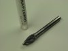
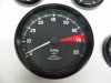
The Speedometer has a small GPS antenna. Since it will easily pick up a signal through fiberglass it was placed under the dash near the gauge in a location where it could be reached from behind the dashboard. A small section of metal was screwed to the aluminum just behind the speedometer since the antenna has a magnetic attachment.
One can wire the GPS so that it will maintain its last position decreasing the time needed to obtain a fix when powered up. We took advantage of this feature, but included a small SPST switch so that it could be disabled. For typical summer use, it will likely be left on, but when driven less frequently over the winter months it will be switched off to avoid battery drain.