Columbus Ohio RCR40

I like #3, but there is a concern.

The return will be a little unpredictable if you just Y it and unless you add a diverter valve to put it back into the tank you're pulling from, or just return to the primary and have some electronics to shut the secondary tank pump off when the primary tank is full. If not and you have 3/4 tank in both and forget and leave the secondary on, you could overfill the primary to the point it's burping out. A simple float switch and relay can handle this.

But having 2 jockey pumps, one from each tank to the swirl pot is my preference once you eliminate the overfilling issue.

I'll be welding my own swirl pot, so I'll just include a 5th port and level sender and eliminate the check valves. For that matter, I'm using Bosch 044 pumps and I'm pretty sure they have an integral check valve.
I share your concern with the return line. I really want to avoid worrying about overfilling a tank as you pointed out. Still thinking about an exact solution... I agree a float switch will do it, good idea.

Do you have a part # for the 044 pumps? The bosch pumps I am finding are twice as expensive as the Walbro pump I found.
An integrated check valve would be nice. Should also work to keep one pumps from filling the other tank other than the swirl pot.
 
I like 1, basic 2 pump system with a Pollack valve. With any of these, what controls the level in the surge tank and what tells the surge tank to return to the main tank and what drives that?
Agreed. currently my front runner.

In my mind nothing is wrong with letting a return line from the surge tank connect to whichever tank is being drawn from. I plan to just have the return line port connect at the very top of the surge tank so it is only used when needed.
 

Sorry for the long polluted link. The outlet fitting is a bit unique, but it works great with a banjo fitting.

The raised rib make it an excellent choice for mounting semi internal. I machined an aluminum mount that will weld into the tanks where a top ring, an O ring, and the raised rib will mount and seal it with a sock on the bottom.

This listing shows what I'll be making.


Ian Anderson

Lifetime Supporter
I like 1, basic 2 pump system with a Pollack valve. With any of these, what controls the level in the surge tank and what tells the surge tank to return to the main tank and what drives that?


Hi David
The idea of a swirl is to constantly move fuel from tank to swirl and a constant overflow from swirl back to tank (This return is always from the highest point on the swirl thus removing any bubbles back to the main tank)

The return line should be able to flow the same as the feed line (No restriction)

Ian
 
I like the keep it simple stupid approach. I had the driver side tank modified to install an in tank aeromotive pump with its own reservoir and check valves ( eliminates the need for a swirl pot or other type of external reservoir of fuel). The passenger side tank simply has a low pressure pump that will transfer fuel to the driver side when needed. I disagree with the idea of redundancy, it’s a car not a plane. How many fuel pumps does your daily driver use? I originally had it setup in a more complex manner and then saw someone else do it this way so I promptly reworked mine with the simpler solution.
 
When do you think the car will be done at RCR? I hear they are backed up with orders!!!
They told me this October when I ordered but I still have not heard from them... I was expecting a delay especially with supply chain nightmares but definitely hopeful to start this winter still...
 
Status update. Planning slowed down a lot. It was a busy summer with work and getting married lol.
When I could I've been thinking more about the fuel system, electrical system, and most recently the engine lubrication system.

Fuel system:
A lot of smart people had some good input on the different options I posted awhile ago. I am considering a 5th option now... I am already going to have a pretty powerful computer onboard (Holley dominator) so it wouldn't be that hard to let the computer turn on and off a transfer pump to a main tank... I am weary of the "pollock" valve solution as it requires a lot more plumbing and I can't for the life of me get any confirmation on the restriction of it. Not out of the question, but currently I am liking the idea of running fuel level sensors that can communicate with the ECU. The sensors that come with the kit are 240-33 ohm but the circuit that outputs a variable resistance according to fuel level is designed to have a relatively high current draw. (Like from a needle gauge). I was concerned about how the sensor will react to a lower current draw of the ECU. I got ahold of a really nice engineer at Centroid and we discussed the matter. We decided it was best to run a similar level sensor but one that simply outputs a 0-5V signal. My ECU should have no problems working with that. This solution presents a new challenge... The needle gauges that come with the kit are meant to work with the 240-33 ohm senders... So maybe I have to have 2 sensors in each tank. Not exactly ideal. More thinking to do here. But if I get a good signal to the ECU it will be simple to have it control a transfer pump to keep it full of fuel. This way I can't be a dummy and forget to turn off the transfer pump... but of course it is very tempting to keep this solution as simple as possible and just do the semi-common method of a single transfer pump manual switch.

Electrical system:
I am very weary of letting even a drop of electrical noise get to my sensors or ECU. A very very broad initial schematic I have planned is below. I will ground the block with a clean ground straight from the battery. And then on a different location also ground it to the chassis. This should hopefully set a foundation for clean grounds. I just then also have to be careful with all grounds from inductive loads... certainly every fan. It is crazy how much EMI those ground wires can produce. Assuming I end up running a DBW TB this is an even larger concern.
Just in case the ECU main power goes straight to the battery posts so the battery can be a last attempt to clean up any noise.
Lots more work to do here. I am a big data geek so there will be lots of sensors and wiring to do... I want the ECU to be able to monitor a large majority of the car. Everything from fuel temp/pressure to tire temp.

1662517543515.png


Engine Oiling system:
I recently have been getting more serious about what to do for the oiling system on the engine. I learned recently that I didn't do enough homework on the rest of the engine when I built the drivetrain to rev out to 7500 rpm (dumb). The stock LS oil pump will reportedly begin to cavitate at 6000 rpm... This fact pretty much makes a dry sump a requirement in my case. Of course that is on top of the well documented issues the stock wet sump system has with oil starvation during performance driving. I have started looking at a Aviaid dry sump kit as a result. The kit is so cool, and provides a new 3/8" port on the adapter plate that bolts to where the original oil filter would mount. (it comes with a remote in line oil filter mount). This way I can relocate the oil pressure sensor and monitor how the oil is doing prior to getting to the block. This would be a combo sensor, pressure and temperature outputs. Right after the oil filter would be the oil cooler... it would be neat to also grab oil temperature here with another sensor to see how effective the cooler is... but maybe overkill. very broad and crappy schematic below. This is assuming I go with a dual scavenge and single pump stage kit. I can get a oil cooler kit that comes with a thermostat switch to control the fan... but I like the idea more of letting the ECU monitor things and control the fan accordingly...

1662518530442.png
 
It was a really big day today as we got our car picked up!!
We were so excited we couldn't help but leave Columbus at 5am to show up a little after 9am. Fran joked around saying "You're not excited at all, I can tell" lol.

The car is home and we happily dug into it and all the parts (while trying to balance family thanksgiving prep).
It looks awesome and we couldn't be happier.

Our enclosed trailer is not a traditional car hauler, and honestly pretty small. Admittedly I was nervous about how the car would fit despite confirming ahead of time with measurements. Eventually we plan to install +2 flares and with them installed there should be only an inch on either side at the doorway. It is tight but we can make it work. Anyways as you can imagine it was a relief to see the car go in the trailer.

Upon getting home we finished going through the packing list and confirming parts, so now the next step is to set suspension/ride height. After that we will tear the car down to the frame and start fitting body panels/firewall. Also on the short list is to get the transaxle some more support , probably by throwing the engine in temporarily.

Got talked out of camping out in the car with a sleeping bag tonight...
 

Attachments

  • IMG-1107.jpg
    IMG-1107.jpg
    453.1 KB · Views: 346
  • IMG-1091.jpg
    IMG-1091.jpg
    584 KB · Views: 351
  • IMG-1088.jpg
    IMG-1088.jpg
    440 KB · Views: 359
  • IMG-1087.jpg
    IMG-1087.jpg
    472.4 KB · Views: 386
  • IMG-1075.jpg
    IMG-1075.jpg
    553.9 KB · Views: 311
  • IMG-1031.jpg
    IMG-1031.jpg
    502.1 KB · Views: 305
  • IMG-1029.jpg
    IMG-1029.jpg
    344.9 KB · Views: 308

Vinny P

Supporter
It was a really big day today as we got our car picked up!!
We were so excited we couldn't help but leave Columbus at 5am to show up a little after 9am. Fran joked around saying "You're not excited at all, I can tell" lol.

The car is home and we happily dug into it and all the parts (while trying to balance family thanksgiving prep).
It looks awesome and we couldn't be happier.

Our enclosed trailer is not a traditional car hauler, and honestly pretty small. Admittedly I was nervous about how the car would fit despite confirming ahead of time with measurements. Eventually we plan to install +2 flares and with them installed there should be only an inch on either side at the doorway. It is tight but we can make it work. Anyways as you can imagine it was a relief to see the car go in the trailer.

Upon getting home we finished going through the packing list and confirming parts, so now the next step is to set suspension/ride height. After that we will tear the car down to the frame and start fitting body panels/firewall. Also on the short list is to get the transaxle some more support , probably by throwing the engine in temporarily.

Got talked out of camping out in the car with a sleeping bag tonight...
Looking good Nick! Enjoy the build!
 

Randy V

Moderator-Admin
Staff member
Admin
Lifetime Supporter
Congratulations!
When setting the suspension ride height, don’t forget that you will need to get your caster, camber and toe settings roughed in before you start dialing in the body positions…
 

Chris Kouba

Supporter
When setting the suspension ride height, don’t forget that you will need to get your caster, camber and toe settings roughed in before you start dialing in the body positions…

I would go so far as to say it should be truly aligned before starting any body location work. Get your wheel positions squared up, set your wheelbase, toe, ride height, etc... Having the wheels and tires in their correct locations is critical to avoiding lots of work later- like tires rubbing on wheel wells in compression or hitting the sills when adding steering lock. It has all happened.

And congrats!
 

Neil

Supporter
I would go so far as to say it should be truly aligned before starting any body location work. Get your wheel positions squared up, set your wheelbase, toe, ride height, etc... Having the wheels and tires in their correct locations is critical to avoiding lots of work later- like tires rubbing on wheel wells in compression or hitting the sills when adding steering lock. It has all happened.

And congrats!
...and adjusting all that is much easier when the body is off.
 
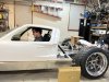
A lot of work has been getting done. It's funny, every next piece of the body you move onto comes with a new unforeseen complication.

This is a big update as all the body panels are mounted except for the doors. (If you can't tell we are really excited to have this project going finally lol my wife is joking that she has been replaced by the car). This project has certainly done it's job of being a great excuse to spend more time with my dad across town. We have a "GT40 night" once a week after work, and squeeze time in on the weekends here and there.

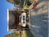
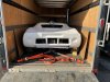
The first thing we did was build a rolling table of sorts to get the car up off the ground and make it easy to move out of the way when it isn't being worked on. Nothing fancy, especially compared to the gulf livery lift built by @Mstarkey3 LOL.... The caster wheels unfortunately have a pretty low weight rating. With 6 of these the table is technically only rated for about 2000 lbs... curious to see how they hold up. It rolls with ease, even over the cracks in the floor. So far we are really happy with it.

IMG_1128.jpg

IMG_1124.jpg


The first thing on the car we worked on were the rockers as these set up positioning for the rest of the body panels. Before we did this we set up the front suspension to the recommended specs and got the lower control arms parallel to the ground (thanks everyone for the advice on this. This turned out to be SO critical). Our new alignment tool still hasn't arrived so we had to get by with the Iphone level app. (It only measures down to the nearest degree so not terribly precise but good enough for now). Front currently set to -1deg of camber and +4deg of caster.

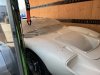
The hardest part of the rockers/front clip by far was getting the Toyo Proxes R1Rs (225/45/R17) to fit... for awhile moral was quite low as we could not make it fit well enough without major modifications to the front clip.

IMG_1161.jpg


The breakthrough was setting the rockers just right, and slightly adjusting the position on the passenger side rocker leading edge so the entire panel could be set further to the rear. Very happy to report that the wheels/tires currently fit GREAT and the clip will possibly not even need trimmed. There may still be a very small amount of rubbing on the inside of the wheel well where the gas tank lid mounts, but only a fraction of an inch. The current plan is to circle back and make a new plate out of thinner aluminum and "dish" it so there is plenty of clearance.

With the rockers and the front clip set we got to work on the spider. There was some trimming needed. The same lip that @Mstarkey3 had to cut off the rear of his spider was fighting us as well so that was first on the chopping block.

IMG_1171.jpg


After measuring the spider about 100 times we finally committed and screwed it into the car with temporary self tapping screws. A 1/8" spacer was installed under each B pillar and two were used on each side.

IMG_1205.jpg


It's incredible how much the spider tightened up after mounting it. It feels completely different and very sturdy. A big key for us in getting the spider to match up well with the front clip was to clamp down the B pillars FIRST, and then tighten down the front of the spider. It was interesting how large of a difference this made.

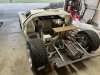
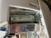
The rear clip was next, and this led to several new big issues. The first one was rear tire fitment (Toyo Proxes R1R 275/35/R17). The wheelbase was at 96" and the rear tire fitment was far from ideal initially as you can see below.

69248209934__E90E5DC7-5E3D-4C55-9CC8-2A941AC59CEB.jpg


We figured at first either the rear clip was too short or our suspension was out of adjustment. We had it at -1deg camber and +6 caster but again the wheelbase was off by an inch. The first choice is obviously to dial in the wheelbase, however it was puzzling because we were out of thread on the lower rear trailing arms so there was no way to bring the rear wheels forward to get closer to the typical wheelbase of 95". We knew something wasn't right as even with the bars at their minimum length the lower rear heim joint on the upright had to be brought out quite far to get the toe in check. Lastly the lower control arm was visually angled strongly to the rear of the car. I don't really have the best photos of this to help explain... I need to be better about taking photos.

IMG_1218.jpg


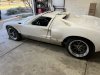
The point is there were many indications that the rear wheels needed to move forward a good ways. Long story short, after tinkering with the suspension for a long time, slightly trimming the lower trailing arm bars, and adjusting the suspension again to the same specs, all the pieces finally came together. It was SUCH a relief to have the entire body fitting so well.

IMG_1241.jpg


Actually mounting the clip on it's hinges went smoothly, except the first time we tried to mount it we forgot the make sure it would clear the aluminum angle iron that spans the edge of the rear under tray when opening. When we went to shorten the rods holding the end of the under tray to raise it up we noticed the heim joints were bound up and the mounting brackets needed modified to reduce the angle.

IMG_1235.jpg


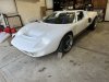
Earlier this week we left off beginning to mount the doors. The hinge system looks great. I read a few people have had luck using one long bolt to keep each mount parallel which I might give a shot. Hopefully soon I will have updates on the doors being installed. Right away at it is clear a lot of material needs to come off the doors to help them fit.

I am excited to get all the body panels hard mounted so we can then start perfecting body lines and panel fitment. Going to be ordering door seals soon to help make sure we get the fitment just right.

Lastly, I would like everyone to meet the chief engineer/supervisor of this project. An Aussie is always the hardest worker in the room and demands perfection at all times. The true brains of the operation. I think we are in good hands...

IMG_1237.jpg
 

Paul T.

Supporter
They appear to be Vintage Wheels out of California.


Any info on the brand and size of wheels?
 
Lots of bodywork getting done!

The doors are hung and starting to really take shape. I am really happy with the hinges and how they work. The hinge mount that bolts to the chassis needed to be ever so slightly drilled out to let 0.5" bolts drop through cleanly. On the passenger side I needed an 1/8" of shim behind the mount and the drivers side needed none.

img_1238-1-jpg.126845


The plates that sandwich the fiberglass on the doors needed the same treatment where I needed to ever so slightly drill them. Once the bolt is tightened there is virtually no slop in them. I got a small amount of binding on the drivers side door at first but all it took was some aggressive sanding to level out the upper mount as seen below.

IMG_1267.JPG


IMG_1265.JPG

IMG_1272.JPG


The outlines of the door panels needed a ton of work. I bet in some areas I took off over a 0.5" of material. No worries as removing material is certainly easier than adding it!! Here is a before an after, still lots of work needed to get the lines perfect. Shooting for about 1/8" of a body gap around the whole car.
Side note I ended up ordering 25' of 1120A431 ( 1/4" edge and 5/8" bulb) from McMaster car after reading this was a popular choice for weather stripping. 25' was perfect for around the rear lid and both doors. I am extremely happy with it. The edges of the spider where the weather-stripping mounts to was very inconsistent from the supplier. I had to work hard to sand it down so the weather stripping could fit over the edge in several places. I am not sure what seal I will use for along the bottom edge of the door, as well as around the front clip, but that's for a later time. The lip of this weather stripping grabs the fiberglass extremely well, and holds it shape.

IMG_1244.JPG

IMG_1250.JPG


IMG_1251.JPG


The top of the drivers side door matched up perfect right from the beginning, but the passenger door top decided it wanted a fight. A few rounds with a heat gun and some shims wedged in the door gap has sorted it out mostly. A tad more work needed here.

Before and after:
IMG_1310.jpg

IMG_1320.jpg
 

Attachments

  • IMG_1238 (1).jpg
    IMG_1238 (1).jpg
    372 KB · Views: 676
  • IMG_1321.jpg
    IMG_1321.jpg
    369.5 KB · Views: 212
Back
Top