DAX40 Return to the Road

Dave Bilyk

Dave Bilyk
Supporter
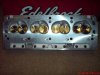
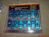
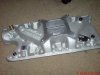
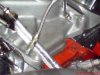
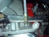
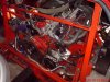
Latest installment, I took advantage on a good price for Edelbrock performer heads and manifold and a set of roller rockers. After a small issue with the existing carb adapter overlapping the new manifold and unable to draw vacuum, the engine runs really sweetly, tickover is smooth and on throttle there is clearly a big increase in torque, power and rev range.
http://www.gt40s.com/forum/gt40-tec...t/25440-question-fitting-performer-heads.html

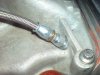
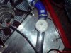
I went down south to my fathers this weekend, but despite the engine now running 10deg C cooler (now 75degC) I had a boilup when I ran into a traffic jam. Unsure of the cause I took the step of drilling holes in the thermostat for the journey back. After doing this, and despite all the checking I had done in days previous, I found that the radiator hoses leaked when hot. I learnt big time to tighten hose clips with a socket wrench, not a screwdriver!
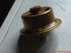
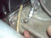
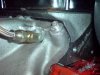
Anyway, I notice that the thermostat seems quite small, and given the fact that with the holes drilled it is massively overcooled, there is so much capacity in the radiator that is untapped by this thermostat, so I have ordered a Mr Gasket high flow thermostat. Also I have removed the bleed nipple from my old radiator and am about to to install it in the rear of the inlet manifold, another idea from this forum. Thanks to Roy Smart and Paul Thompson for their advice on this issue, and to Jacmac for his advice while installing the heads and setting the lifters.

Dave
 

Attachments

  • GT40 009.jpg
    GT40 009.jpg
    38.4 KB · Views: 411
  • GT40 011.jpg
    GT40 011.jpg
    52.7 KB · Views: 425
  • GT40 014.jpg
    GT40 014.jpg
    41.2 KB · Views: 401
Dave, did you fit and air bleed from the rear of the manifold back to the header ? as the edelbrock inlet manifold doesn't have a coolant passage there.
Air can get trapped there with no way out otherwise.
 

Dave Bilyk

Dave Bilyk
Supporter
Thanks Paul,
that would be useful to compare with my measurements.
Of course I would take total responsibility for doing the deed, and will take the manifold off if in any doubt at all.

Dave
 

Dave Bilyk

Dave Bilyk
Supporter
Today I received the replacement high flow thermostat. On testing in boiling water, I see that the opening is about twice the diameter and twice as deep as the old one, which means about 4 times the flow area which ought to help.
 

Attachments

  • gt40 005.jpg
    gt40 005.jpg
    22.7 KB · Views: 367

Dave Bilyk

Dave Bilyk
Supporter
Having fitted the thermostat I left the engine idling to see at what temperature she stabilised. Less than 95deg as near as I can read the gauge, ambient was 15deg.

Dave
 
Just had a chance to get some measurements. My bleed lines are approx 40mm in from the rear of each head and 33mm high from where the head meets the head gaskets. It's a bit of an awkward spot to fit pipes here as the surface has the curved bit where the top of the manifold runs upto the inlet face of the heads. Mine are counter sunk so as to get a flat face to seal onto. My fittings also have a nut on the inside which require manifold removal to get to. It would be posible to drill and tap the manifold but my recomendation would be removing the inlet to do this job firstly for accuracy and also so as to not get any swarf into the coolant passages.
 

Attachments

  • DSC00318.jpg
    DSC00318.jpg
    42.2 KB · Views: 388
  • DSC00316.jpg
    DSC00316.jpg
    52 KB · Views: 393

Dave Bilyk

Dave Bilyk
Supporter
Paul,
thanks, that is perfect, mine is the same manifold, so the pics are exactly what I needed for confirmation. The RHS with the web is the tricky one. Provided I can get the angles right, and your pics and my old gaskets and pictures of the heads give plenty of clues for that, I would be happy to do this without removing the manifold, as plently of grease and drilling and tapping in stages before finally breaking through would prevent significant swarf from entering the passages. But I may or may not have time to do it before Lemans, we willl see.
On getting my aircon pressure checked, I found a leak at the compressor, so that is away for fixing, other than that, she is ready to go.

cheers
Dave
 

Dave Bilyk

Dave Bilyk
Supporter
Ok,
I have the bits and pieces now, a 1/8" NPT tap, and an 8.5mm drill (nearest to Q size 0.332" = 8.433mm so only a few thou in it), but time is short and I don't really have time to put the tappings in the thermostat housing end. I could however do the inlet manifold tappings and connect them together which would be a half way step and might do some good if it creates some small circulation between the heads. Any views on this?

Dave
 

Ian Anderson

Lifetime Supporter
Dave

Surely the other end of this should go back to the header tank.

And I believe the return to the header should be restricted severly to about 1/16 inch hole to stop a different flow than that originally envisaged

Perhaps just a T into an existing pipe at the header would work.

Ian
 

Dave Bilyk

Dave Bilyk
Supporter
Ian,
yes, on reflection I see the sense in that. If the idea is to get rid of air, then the header tank is the place to do it. Also the restriction to limit the flow makes sense. If I do it this way, I could do it in a reasonable time, so if I can find a tpiece or two....
thanks for that.
Putting a rear view camera in now as when driving to my dads and back I was appalled by the blind spot I have.

Dave
 

Ian Anderson

Lifetime Supporter
Dave

T Pieces

Car builder solutions or Think Automotive are the ones I've used but then again most good auto factors should be able to get them

Ian
 

Dave Bilyk

Dave Bilyk
Supporter
Thanks Ian,
but since we are leaving tuesday, I am out of time to get parts and fit them as we now have to concentrate on other things, but what I did this afternoon was to drill and tap the passages, and fit a pipe between the two heads. Maybe it won't self bleed, but at least it gives me the means to bleed the heads properly, so I am happy with that for the trip to Lemans. Thanks to Paul for the pictures which gave me the confidence to drill the holes:thumbsup:

In the morning I finished fitting the rear view camera system and that seems very good both night and day. Last week I also fitted a high level Brake light, tucked in unobtrusively at the front of the rear clip inside the window.

Dave
 

Attachments

  • gt40 003.jpg
    gt40 003.jpg
    37.1 KB · Views: 409
  • gt40 004.jpg
    gt40 004.jpg
    40.9 KB · Views: 377
  • gt40 005.jpg
    gt40 005.jpg
    46.7 KB · Views: 379

Dave Bilyk

Dave Bilyk
Supporter
Fired up today and temperature seemed to stabilise 2 or 3 degrees cooler (effect of proper bleeding of heads?) went for a run and never got any hotter than 90degC in traffic, 75 cruising.
I found a useful thermometer that came from my old central heating system. Its a pipe thermometer that can be clipped with a light tension spring onto a radiator pipe, there is a brass pad on the back to contact the pipe and readout is a dial face as in the photo. I dont know how accurate either of the gauges are, but at the inlet to the radiator, I had 94degC on the pipe thermometer.


Dave
 

Attachments

  • GT40 001.jpg
    GT40 001.jpg
    46.7 KB · Views: 374

Dave Bilyk

Dave Bilyk
Supporter
Now the weather has warmed, I re-started work on the car. My next task is to fit 6 point seat belts.
This means 3 additional anchorage points as the car was only fitted with lap and diagonals.
I bought a Willans 'Silverstone' type belt, and having studied the installation leaflet I find that;
Existing anchor points either side of the seat are correct for the lap belts.
Existing anchor point for the inertia reel is ok for one crotch strap mount.

Additional anchor points required are for the inside crotch strap and the two main chest straps .
The sheet says that the chest strap mountings should give an upward angle of 20deg from the anchor point to the shoulder.
To achieve this I have to weld in additional tube, so I am considering my options at the moment.
Today I completed removing the bulkhead to get access.
Attached is a photo of the gaping hole, and Solidworks renderings of the chassis area as it is, and one option for mounting the chest straps.
My plan is to weld in solid bar tapped for the eye bolts as is used on the existing anchor points.

regards
Dave
 

Attachments

  • 037w.jpg
    037w.jpg
    108 KB · Views: 465
  • original.jpg
    original.jpg
    22.8 KB · Views: 450
  • mounts.jpg
    mounts.jpg
    24.3 KB · Views: 425
Last edited:

Ian Anderson

Lifetime Supporter
Dave

From you picture it looks wrong.

I have a single mount on the existing cross bar (immediately under the wndow) and it is at shoulder type height

Ypurs looks like it would be half way down your back.

So your belts would go up from the anchor to your shoulder then back down to the buckle - in an shunt both would act to "shrink" your spine

That said I'm the accountant and you are the engineer!

Ian
 
Hi Dave

I think the angle they are looking for is 20 degrees down from the horizontal from the point on your shoulder to the mount; that would put the mount on a line just below the window.

Trust all's well with you

Steve
 
Back
Top