
You are using an out of date browser. It may not display this or other websites correctly.
You should upgrade or use an alternative browser.
You should upgrade or use an alternative browser.
Don's Mk IV Build
- Thread starter Don Nye
- Start date
- Status
- Not open for further replies.
D. Nye
Lifetime Supporter
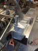
The first task after receiving the car was to take it apart which I considered the first step. Seeing all the projects I started working on the tanks install. I have been looking at using a AN 16 size line between tanks and it appears there is room to run the line outside the cockpit in front of the engine, still working on it. That's just one of the challenges of a Mk IV with only one filler. Original cars had this line running under the seats which was the first idea but since there is a way around the cockpit it's the new plan.
The holes are cut and tanks slide in and out fine. I found the tanks are 44 1/2" long while the side pockets where the tanks fit is 48 1/2" long which gives us 2" front and back. Someone did the math because the filler hole lines up where the tank sets when centered in the side pocket. Doing the volume calculation the tanks are about 10 to 11 gallons each. Tanks will have fuel cell foam as others have done.
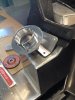
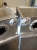
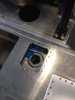
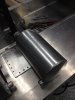
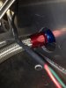
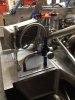
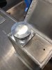
Been searching for fuel lines and fittings. The tank fuel supply opening are tapped 7/16"-20, and best I can see require a o-ring fitting like used on carburetor supplies, see attached photo. Vent is tapped 3/8" which is easy to plumb. The fuel sending unit needs to be cut to length and I tapped the screw holes for 10 x 24 x 1 1/4" long screws.
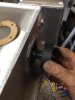
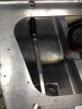
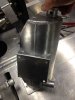
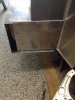
The supplied filler neck will require a lot of modifications to make it fit in the space available, see photo. But like all things with the build everything is custom by the time it is done.
The holes are cut and tanks slide in and out fine. I found the tanks are 44 1/2" long while the side pockets where the tanks fit is 48 1/2" long which gives us 2" front and back. Someone did the math because the filler hole lines up where the tank sets when centered in the side pocket. Doing the volume calculation the tanks are about 10 to 11 gallons each. Tanks will have fuel cell foam as others have done.
Been searching for fuel lines and fittings. The tank fuel supply opening are tapped 7/16"-20, and best I can see require a o-ring fitting like used on carburetor supplies, see attached photo. Vent is tapped 3/8" which is easy to plumb. The fuel sending unit needs to be cut to length and I tapped the screw holes for 10 x 24 x 1 1/4" long screws.
The supplied filler neck will require a lot of modifications to make it fit in the space available, see photo. But like all things with the build everything is custom by the time it is done.
Attachments
MK-4's are beautiful, have had the pleasure of being right behind one at Road Am. in my small formula car, and watching the back end squirm around under braking, and the sound as it fired up the hill from 5 to 6.
D. Nye
Lifetime Supporter
It's been a while and a few have sent messages wanting updates so I took some pictures last night to give everyone a look at what I have done to date. The calendar has been full of family things so I'm going slower than I want but still have all the joy of a kid with his new toy.
I continue to work on the gas tanks and take a break because I get interested in seeing what things might look like so I have these small distractions but one of the main reason you get to a point where you need to order more parts.
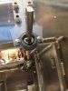
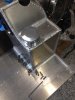
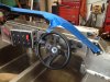
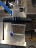
The steering column was one of those jobs I was waiting on parts and once in hand I installed, see attached pictures. The parts where all provided by RCR except the 3/4" coupler nut and 3/4" bolt to hold the middle section of the column.
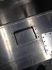
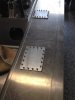
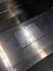
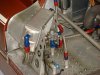
I have cut access holes and made the covers over the gas tanks to provide access to the sending units and a new access hole I'm making about mid tank, one to secure the back nut to the equalizing line and to service the fuel cell foam I'm planning for the tank. With all I have read on the web I may need to replace the foam in the future and the middle access port is for this very task. I also install the fuel fill which worked out great.
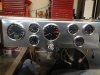
I'm also one of those guys that likes to eat the dessert first so last night a made the gauge section of the dash and set everything in the car just to see what it might look like. The original cars did not use this many gauges but I decided to utilize what I had and copy come of the form the original cars had. RCR provided all the gauges plus an additional fuel gauge that I'm not going to use. The fuel system will utilize the left tank as the reserve tank just because it will always hold more fuel because the equalizer line is not at the bottom of the tanks. More on that subject next time.
You are now up to date, enjoy, I am!
Don
I continue to work on the gas tanks and take a break because I get interested in seeing what things might look like so I have these small distractions but one of the main reason you get to a point where you need to order more parts.
The steering column was one of those jobs I was waiting on parts and once in hand I installed, see attached pictures. The parts where all provided by RCR except the 3/4" coupler nut and 3/4" bolt to hold the middle section of the column.
I have cut access holes and made the covers over the gas tanks to provide access to the sending units and a new access hole I'm making about mid tank, one to secure the back nut to the equalizing line and to service the fuel cell foam I'm planning for the tank. With all I have read on the web I may need to replace the foam in the future and the middle access port is for this very task. I also install the fuel fill which worked out great.
I'm also one of those guys that likes to eat the dessert first so last night a made the gauge section of the dash and set everything in the car just to see what it might look like. The original cars did not use this many gauges but I decided to utilize what I had and copy come of the form the original cars had. RCR provided all the gauges plus an additional fuel gauge that I'm not going to use. The fuel system will utilize the left tank as the reserve tank just because it will always hold more fuel because the equalizer line is not at the bottom of the tanks. More on that subject next time.
You are now up to date, enjoy, I am!
Don
Attachments
D. Nye
Lifetime Supporter
mmiller, I take measurements have an idea what it should look like than draw it up in CAD. Print full size, cut out a pattern like a dress maker and mark and cut out aluminum part. I use a fly cutter at the drill press and a little metal break to fold it. I'm not a master but getting better at if. The dash took me about an hour to make once I had the paper pattern made. Glad to share a copy of the drawing if you need it.
I'm looking forward to reading your build, keep us posted.
Don
I'm looking forward to reading your build, keep us posted.
Don
D. Nye
Lifetime Supporter
David your welcome anytime, just give me a call before to check if I'm home.
Still working on the fuel tanks getting them installed, getting close. I attached a simple diagram showing how the fuel system is being installed. One pump with electric tank switch over valve for those times when I need to run on reserve.
I'll post pictures of the complete tank install when complete and list of parts used to help future builders.
D
Attachments
D. Nye
Lifetime Supporter
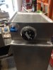
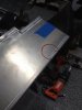
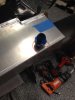
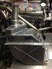
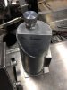
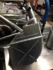
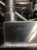
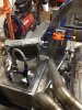
I just had to post some pictures of what came in the mail yesterday. One of the areas I wanted to copy was the right rear area of the engine bay and because I'm not an aluminum welder I contacted Kenny to build me some oil and water tanks. I want to copy the J7 car as close as I can so I told Kenny to build the tanks like the HM cars were done. There is a difference if you look at the old photos. Anyway I'll work on fitting the tanks after the fuel tanks are completed.
I think Ken was a little set back when I asked him to sign the tanks. He could not understand why I wanted him to sign, I told him he had paid his dues with these cars.
I now know what size they are.
I think Ken was a little set back when I asked him to sign the tanks. He could not understand why I wanted him to sign, I told him he had paid his dues with these cars.
I now know what size they are.
Attachments
D. Nye
Lifetime Supporter
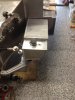
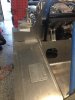
Gas tanks are in. Just waiting for the filler hose and the right front tank cover can be mounted. All the fuel lines are routed through the chassis and I'm waiting on the last few AN fittings to finish plumbing the fuel filters and pump. The equalizer line and right tank fuel supply fit in front of the engine and I will mount the holding brackets once I have all the other plumbing lines routed through the center tunnel.
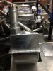
Last night I mounted the oil tank and very happy with the way it looks. I think it's a credit to RCR that the original part can be fit in their car not with out some cutting but it can be fitted.
Next job will be all the other plumbing, brake lines, cooling pipes, AC lines and electrical wiring through the chassis.
Attachments
D. Nye
Lifetime Supporter
Thought I would share a couple photos of last night’s work. Fuel lines almost to engine. The last photo in the group is one I took of J7 last summer just to compare what my car will look like compared to an original. A cleaner look with the check valves below the lid and using only one fuel pump and other valves installed out of sight. Still gets tight with the oil cooler.
Attachments
")
D. Nye
Lifetime Supporter
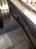
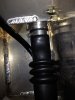
Got somethings done this weekend with the completion of the fuel system. One of the things I had trouble with was finding a flexible filler hose. First tried Gates filler hose, not flexible at all! Tried advertised flexible hose from Tank Inc., same as Gates hose. I read many build logs where people have used combination of straight hose and hard ells or 45 deg hose with straight hard pipe. My search ended when I found Bob Drake filler hose, see attached pictures. Very easy to install and made the offset easy. Just hoping this helps someone from searching a week.
The front cover plates are mounted and I can say the fuel system is ready for fuel up to the final fuel filter.
I have moved on to the brake system and will post pictures later.
The front cover plates are mounted and I can say the fuel system is ready for fuel up to the final fuel filter.
I have moved on to the brake system and will post pictures later.
Attachments
- Status
- Not open for further replies.
Similar threads
- Replies
- 12
- Views
- 965