
- Forums
- GT40 Replica Manufacturers' Corner
- RCR Forum - RCR40/SLC/917/Superlite Aero
- The SLC Clubhouse
You are using an out of date browser. It may not display this or other websites correctly.
You should upgrade or use an alternative browser.
You should upgrade or use an alternative browser.
Dusty's SLC Build
- Thread starter Dusty
- Start date
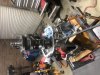
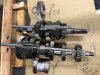
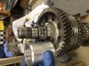
Mailman delivered the drop gears and the pair of 6the gear overdrivers a few days ago so I strapped the Graz to the bench and started taking out bolts. So far so good. The procedure starts on about page 160 of the transaxle manual. These is some special socket to remove the pinion Lock nuts but I don’t have it (anyone know where I can get one??) so I chopped up a big Crescent wrench and it works. I’m sure a big pipe wrench would work too.
From here on out I’m going to follow the Lamborghini video that was posted by someone. Tomorrow I need to go and get a 28 mm socket And a wrench to remove this big bad nut. Once that is done I can pull the case apart and work on the drop gears and sixth gear theoretically. If it works then I’ll post up the entire process and the necessary tools. If I fail then why bother posting it up.
Note that there are four different retainer nuts involved in the disassembly. Each one of those Must be crushed to set them to the shaft once torqued. Note that they are $80 each.
Attachments
Edison wasn't wrong !!!
Bill Kearley
Supporter
A failed attempt could teach all of us.
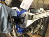
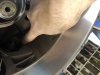
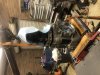
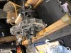
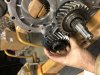
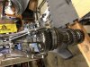
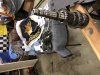
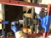
OK fellas. She is coming apart. Note that that big nut I referenced yesterday does not need to come off before you split the case. But if you do not loosen it while it is in the case and held secure you are going to have one heck of a time loosening that nut once you split the case. I loosened it with a 30 mm wrench I bought from Harbor freight and notched the wrench with a grinder as seen in the picture. If you don’t notch the wrench you will not be unable to turn it Once it is on the nut. This is so because the ranch is wedged in there tight in that small hole. I could not get a socket on the nut . And note that you need to turn the nut for about three or four complete turns to loosen that very solid nut. The parallel Gear stacks must be locked together to remove the nut. You do this by engaging the gears to the position as shown in the manual. Once you figure out the gear thing you can easily engage and disengage the gears to lock the shafts from turning While u wrench. Once the nut is loose the wrench will be stuck in position and you will be unable to get the wrench Until you split the case. But that’s OK.
Note that the manual says to bang the pinion out with a mallet. This is easily done. Be sure to put your hand on the pinion gear so you don’t launch the pinion onto the floor.
Note that the ring gear is easily removed. Just take the circle of bolts out and it comes right out. Don’t drop it.
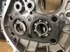
Once that big nut is loose you can remove the five or six bolts as referenced in the manual to free up the parallel gear clusters. Note that the gear cluster assembly is indexed to the aluminum housing below it With several towels. Because of this The gear assembly housing piece is stuck fairly solid to the housing below it. You must make sure that the big housing piece that bolts to the engine is securely bolted down throughout all of your wrenching. If not you will not be able to torque off some of these solid nuts. You could literally bolt the trans axle housing to a piece of thick plywood or to a 2x12 and that work. In my case I have a metal workbench and so I used three large ratchet straps to secure the housing to my workbench.
I used a prybar to pry up against the parallel gear assembly piece once it was unbolted. By doing this I was able to slowly open a crack in the Unbolted mating surfaces and was able to wedge in some plastic wedges. I went around the housing using this technique until I had a good three eights inch gap. Then I carefully pushed a nylon strap through the gap to the other side of the housing and used this strap loop to lift the gear assembly away from the lower housing using my engine hoist. If you have a few friends to help you you could probably skip the engine hoist. That said go slow so you do not damage the dowels that go between these two adjacent assemblies. If you’re not careful you could easily damage the aluminum mating surfaces and cause an oil lead after reassembly.
Note that the manual says to bang the pinion out with a mallet. This is easily done. Be sure to put your hand on the pinion gear so you don’t launch the pinion onto the floor.
Note that the ring gear is easily removed. Just take the circle of bolts out and it comes right out. Don’t drop it.
Once that big nut is loose you can remove the five or six bolts as referenced in the manual to free up the parallel gear clusters. Note that the gear cluster assembly is indexed to the aluminum housing below it With several towels. Because of this The gear assembly housing piece is stuck fairly solid to the housing below it. You must make sure that the big housing piece that bolts to the engine is securely bolted down throughout all of your wrenching. If not you will not be able to torque off some of these solid nuts. You could literally bolt the trans axle housing to a piece of thick plywood or to a 2x12 and that work. In my case I have a metal workbench and so I used three large ratchet straps to secure the housing to my workbench.
I used a prybar to pry up against the parallel gear assembly piece once it was unbolted. By doing this I was able to slowly open a crack in the Unbolted mating surfaces and was able to wedge in some plastic wedges. I went around the housing using this technique until I had a good three eights inch gap. Then I carefully pushed a nylon strap through the gap to the other side of the housing and used this strap loop to lift the gear assembly away from the lower housing using my engine hoist. If you have a few friends to help you you could probably skip the engine hoist. That said go slow so you do not damage the dowels that go between these two adjacent assemblies. If you’re not careful you could easily damage the aluminum mating surfaces and cause an oil lead after reassembly.
Attachments
-
 7DBDC554-B39F-4722-852B-80FB596DB436.jpeg412.8 KB · Views: 452
 -
 E187EDBD-3C1A-45AB-A6BD-67662C4E49FC.jpeg328.1 KB · Views: 457
 -
 D130769B-83DD-4BC2-A35F-876CDF0641ED.jpeg349.3 KB · Views: 438
 -
 955C0649-7ABD-4083-91B3-13E172D7BCF1.jpeg437.4 KB · Views: 466
 -
 3B0EB4DD-A6AD-4F2F-99D4-481AC41D4771.jpeg444.9 KB · Views: 424
 -
 09D8E6A7-0ADF-4344-8DE6-0AAE27F04AC3.jpeg413 KB · Views: 416
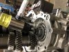
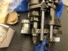
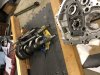
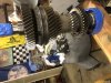
This picture shows the two new gears that need to be installed. And the position they need to be in. I do believe that I will need to cut a few millimeters away to fit this gear set. Probably the least of my concerns right now.
Attachments
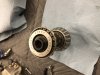
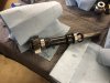
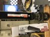
This picture shows the sixth gear overdriver gear set that I ordered. Looks like a challenge to get these on. I’ll figure it out. I must say they are a total work of art. I’m thinking about putting them under the Christmas tree tonight just so I can unwrap them again tomorrow morning with the kids. Speaking of which I have to go help my wife wrap presents for the kitties. Merry Christmas everybody.
Attachments
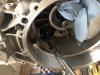
Removing the front drive gear and shaft is very easy. Now I just need to make up a plug or get one from Ron.
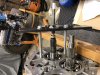
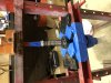
Next I drilled a couple of three-quarter inch holes in a 2 x 4. That secures 1/2 of the gear stack. the other half of the gear stack which goes through the bearing plate was also secured with a 2 x 4 and a couple of bolts going through the 2 x 4 and through A couple of the holes already in the bearing plate. Both of the two by fours were then strap down to my metal workbench so that I could talk off box and press the bearing plate off of the Gear stacks.
Next I drilled a couple of three-quarter inch holes in a 2 x 4. That secures 1/2 of the gear stack. the other half of the gear stack which goes through the bearing plate was also secured with a 2 x 4 and a couple of bolts going through the 2 x 4 and through A couple of the holes already in the bearing plate. Both of the two by fours were then strap down to my metal workbench so that I could talk off box and press the bearing plate off of the Gear stacks.
Attachments
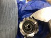
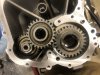
Now you can torque off that big nut off the output shaft. Now you can remove the large gear that needs to be replaced for the drop-down gear modification. If your goal is to replace the drop down Gear set then the tear down job is done at this point and you can start reassembling the case. Here is a picture of the new gear on the shaft next to the stock gear in my left hand.
Attachments
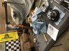
But if you’re replacing the sixth gear with a new overdrive gear then you got to keep going. The manual specs a pair of polars like the one I made to push the input and output shaft out of the bearings. I made one push your tool with a piece of 3/8 inch flat bar I had laying around. I also had a cheap harbor freight puller that I Sacrifice to make the tool. I simply welded the tool to the three eights inch flat bar and you’re done. Takes about 15 minutes to make one. The harbor freight pullers are almost free. You will need a Pair of long 8 mm bolts. But if you play with LS motors a lot there are lots of these bolts laying around.
Attachments
If you only have one pole or you have to go back-and-forth between the two years about six or seven times. Just use a Makita power wrench and you can fly through the process. You have to go back-and-forth Between the two shafts rotating the Puller between the two shafts as you go because remember that the two sets of gears are still messed together. And they only have about 1/8 of an inch Movement before they will bind up. Don’t let them bind up and scratch the gears. Continually hold one set of the gear stack and rotate it in your hand while you are tightening the puller. If the gear stack starts to bind up then you know you need to stop and go to the other shaft. If you’re smart and buy two colors from Harbor freight you can make up a pair of these tools which would’ve been faster.
First gear pulls off easily. Next you can remove the synchronizer hub which just slides right off. Bearings come off easy. Then you have to remove this single Snap ring which is not shown in the manual. Cake. In the manual it shows that they are using a puller to remove second gear. I don’t know why they show that because second gear is splined and just slide right off.
So basically once you have freed the output shaft from the bearing plate you only have to pull one year. Just first gear. The rest of the shaft stack comes off real easy without any more gear pulling.
If I get a chance tomorrow I will use a press to remove that fifth/ six gear and replace it with the overdrive unit.
Attachments
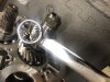
OK here is how I got the output shaft overdrive gear on.
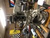
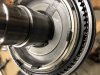
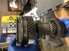
First thing you have to do is push off the old gear. And a 12 ton harbor freight Pres just barely did it. I suggest you use a bigger press. This 12 inch receiver hitch extension (2” ID) from Harbor freight made a great tool to press on the new gear. First you need to heat it up to 260° In the oven as suggested in the manual. The hot gear pushed on much easier than the old year popped off in my case. And note that you don’t need to be careful when you press it on. Just push it all the way on until it seats against the other gear. Note that that last pair of gears on the output shaft are Machined with the shaft as a solid piece so you’re not going to accidentally push them out-of-the-way As you press on your hot overdrive gear.
The picture shows me pressing off the stock gear. The other pic shows how the harbor freight extension fits neatly over the gear stack to help push on your new overdrive gear. Note the direction of the overdrive gear on the shaft.
Attachments
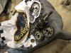
You might be tempted to play with the stack of magic right here. Don’t do that. Take this entire pile off as one piece and put it back on the new shaft after the new gear is pressed on. Don’t take it apart. Trust me. Luckily I took lots of pictures otherwise I wouldn’t of gotten it right. I was A little scared for a while
Attachments
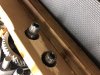
That colar must be pressed on. It’s the piece on the shaft a couple inches straight out from my thumb. That colar holds the whole stacked together. I pressed it on with a water pump seal alignment tool for an LS motor. I put a socket on top of that to finish the job. It presses on easily.
Attachments
This last part is important. You can’t press the whole stack together tight. There has to be a little bit of axial play. The manual specs between .1 and .5 mm of axial play. That’s quite a bit of leeway so I split the middle. At about .3 mm. You can honestly eyeball that much runout if you don’t have a measuring device. So as you’re pressing this last caller on be sure your wiggling the Reverse gear a little bit to make sure that you can still move it. And just press real slow with your press. If you press the The collar down tight on accident you have to put the puller back on the reverse gear and loosen it up a little bit (pull it back off) until you have the proper run out. It is easier to pull the gear off carefully with a 3 jaw puller that it is to push it on carefully with A hydraulic press.
I Used a micrometer On the gears before I took apart the stack. Measurements pre-and post assembly were very close. My run out is the same. Note that these gears are beautiful. I have torn apart transfer cases before to re-gear them and The aftermarket gears I have purchased have never looked this good.
I Used a micrometer On the gears before I took apart the stack. Measurements pre-and post assembly were very close. My run out is the same. Note that these gears are beautiful. I have torn apart transfer cases before to re-gear them and The aftermarket gears I have purchased have never looked this good.
Attachments
Similar threads
- Replies
- 36
- Views
- 8K
- Replies
- 26
- Views
- 8K
- Replies
- 7
- Views
- 6K
- Replies
- 64
- Views
- 18K