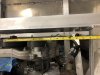
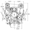
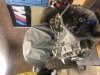
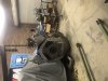
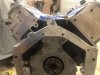
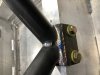
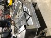
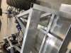
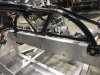
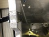
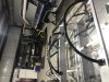
THANKS for the input and the references to other builds. very helpful. I have called several vendors who make a LS corvette (y body spaced) head mount AC bracket. The most narrow of these brackets is 16" wide from the engine centerline to the outside edge of ac bracket. By my measurements it is 15.5" from the engine centerline to the aluminum "frame" of the SLC chassis. (see pic) the reason these brackets are made wide for corvette motor swaps is 2 fold: firstly most people put these motors in the front of a swap or want to mount the ac up high in the vette. In both of that situation hood clearance is paramount. The second reason for the wider spacing is to avoid colliding the ac bracket with the throttle body. Neither of these are an issue in the SLC because there is room in the back of the SLC to move the ac upward and we flip the intake manifold backwards so there is no throttle body to worry about. I put out a call to wegner motorsports as suggested above. im waiting for their response.
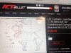
I cant see how the holly bracket will fit-its too wide
ill keep looking but I anticipate the local race shop will be making me an AC bracket when the . they have jedi skills.
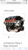
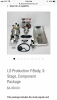
I went ahead today and ordered the Daily Corvette LS Dry sump kit. the guys at daily are very helpful. I highly recommend them.
I cant see how the holly bracket will fit-its too wide
ill keep looking but I anticipate the local race shop will be making me an AC bracket when the . they have jedi skills.
I went ahead today and ordered the Daily Corvette LS Dry sump kit. the guys at daily are very helpful. I highly recommend them.