Ford F3L and David Piper

Hi Mick,

the glueing has a very positive side effect of sealing the gap between the panels in order to keep moisture and dirt out. But it is really not a nice thing to do, all the cleco pins, drills and tooling have to be constantly cleaned when you are assembling some sheets additionally with adhesive. In the end the adhesive should be just between the gap, and nowhere else.

About your question with the L163: 13% elongation is good, but as far as I dould find out this is for the T3 tempered condition (I was wondering, because a T6 tempered alloy with 13% elongation would be the unbelievable). I would consider the T6 stadium of this alloy as non bendable (except with radii as large as e.g. the cross section of an airplane fuselage), so if you want to use it for just flat sheet this will surely be a good choice if you have to have high strength. However if you have to bend, I think you can do it only with T3 or earlier temper stages. These do not have the strength of the T6 version but due to that the higher elongation necessary to bend.

Hope that is the info you needed
 
..the monocoque is coming together quite neatly.
Yesterday, with the finished main bulkhead we checked the gap between the door and the structure. Its good even though the parts were fabricated independent of each other.
 

Attachments

  • IMGP2304.jpg
    IMGP2304.jpg
    31.4 KB · Views: 1,014
Hi Mehmet,

thanks for your post, I have to admit that I have been very lazy lately as far as the internet is concerned.
Don't worry, work is progressing as always, I have been focusing on designing the plumbing and building a mandrel bending tool for the large dia water pipes.
Turned out that I need more geometrical info on all the AN-fittings which I received a few days ago. The mandrel bending tool needs a little rework as I didn't desing some parts with adequate tolerances (indeed some things need more clearance than I produced/designed).
This weekend we will do some more riveting on the monocoque (which we put on idle as I need to fabricate the water pipes first). I will post some current pictures after the weekend.
I attatched a picture of machining the mandrel benders turning die. Well this is from a very early stage, but I didn't take any more pictures after that step. Again, after the weekend..
 

Attachments

  • DSCF0135.jpg
    DSCF0135.jpg
    30.8 KB · Views: 763
..well, we were quite busy yesterday and today. We could manage to fit some more panels, getting ready to install the fuel cell (maybe tomorrow).

..more pictures coming, now we are going for a must to the legendary Hatzhof.
 

Attachments

  • DSCF0145.jpg
    DSCF0145.jpg
    19.4 KB · Views: 797
  • DSCF0146.jpg
    DSCF0146.jpg
    35 KB · Views: 831
  • DSCF0147.jpg
    DSCF0147.jpg
    33 KB · Views: 771
  • DSCF0148.jpg
    DSCF0148.jpg
    37.2 KB · Views: 1,057
guten tag leopold

i am speachless about your work, i follow all pics from this build, gratulation, sometimes i think i am the only cracy in austria, but this is more that i can do,....
i love your 5axis cnc to cut/mill the foam, this is realy a step forward to do job´s like this, i wish you the best, and hope to see pic´s from the ready car

die besten grüsse nach kärnten

ernst from loweraustria
 
Servus Just,

thanks a lot for your nice words.
Well, the CNC machining is a nice thing, but it surely comes at the cost of complexity: believe me, designing a proper body mold ready for machining (including the raw part) is not straight forward. But it is always that way: creating something nice always requires time and attention or in other words to quote the Austrian Army (more as a joke): "Der Zweck fordert die Mittel."

I do really hope we'll be able to show pictures of the finished thing in a good year, maximum two years..., lets keep fingers crossed.

Beste Grüße nach Niederösterreich, ich hoffe du musst dir nicht auch den Weg in die Werkstatt mit der Schneefräse bahnen...
 
hi leopold
yes,...der zweck fordert die mittel...., i see this all around, not only at army,..haha
i wish we had so much snow to makes a tunnel to go in company,...would be a little break for some people outside,....and makes time to think alot about real things,....

hm, i know, it is alot of work, but what i see on all your pics,....you could build a rocketship going to the mars,....yes, i see it on some details, great knowledge and greatest work,.....is this a "tischlerei"?? you worked inside??,....perfekt conditiones to do such a projekt
i build prototypes for some little aplicationes, and we had a lot of tech in some networkcompanys around us, lasercut, cnc-bend, 3d-print,....but what i want to had around is a maschineshop with an 5axis-mill,..hahaha,....for creativ people in fast times like now,....it is the maschine to --must have--,...hahaha,....
i wish you the best with your work, it looks great and perfekt, and the art you do it looks 100% professionell,....this will be a perfekt racemaschine
do you allso have a gt-40??,..... 21 years ago we sell a gtd-kit to kärnten, i call the owner 5 years ago, gt still alive and powerd with an v6 renault engine, upgrade to an hellmobile,....
ernst
 
Servus Just,

:D 
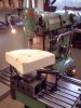
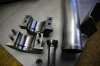
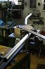
as you say, the CNC machining is surely a nice thing...
Thanks again for the positive comments.
Yes, one winter we worked in a carpentry shop, this had a few reasons: during ply layup we could easily produce a cold ambient temperature, while for hardening we just had to turn up the saw dust fired oven as hot as we wanted.
Second reason was that they had their winter vacation, so the shop was empty, and we could do whatever we wanted. It was very useful to have circular saw, planer and bandsaw/band sander at hand for making the foam cushions.
Third reason: There is surely no trace of silicone in a carpentry shop (unlike in a metal shop), something which is diabolic in comparison to "just" dust particles. Needless to say, we had to clean the room for a whole day in order to get it quite dust free...
On the other hand, what has to be noted is the fact that we had to transport the largest molds there, which is not a real nice thing to do.

Yes, my father has a GT40, however it is not the kit you sold 21 years ago (this was way earlier). Glad to hear it is still alive-
 
greetings Leopold,

i am very interested in your radius form you are making
with the help of your Emco-Maier rotary table ---

what kind of wood did you use?

is it several layers glued together to
arrive at the desired thickness?

and did you cut the radius form on the Deckel style machine?

if you have the time could you please post more pics of the
completed radius form & your tube bending?

thanks very much for a great project!
learning very much as i follow.

scott
 
Hi Scott,

sure thing, i didn't post more as I thought it wouldn't be of interest.
Just give me time till mid of Jan, because I have no time to go home before that (and I don't have any more pictures of this tool on my PC).

Very well seen, the rotary table is an EMCO type, although it was nearly too small. I had to tighten the friction quite strong to keep it from vibrating during the machining.
The radius was cut after the picture above was taken, with the horizontal spindle (you have to dismount the head to use it). As I couldn't do it in one cut (too much cutting load as well as the lack of a radius cutter that large) I did it with a R6 radius cutter and used the pitch circle option on my DRO. I know, it is intended for drillings, but it worked fine for this purpose.
The material is multi layer birch plywood (as used in aircraft), because this wood has the highest youngs modulus of our domestic woods in Europe. At the beginning I wanted to use POM plastics, but the material would have cost me 95€, so I decided to go for birch wood, as the y-modulus of the latter is higher anyway.

I'll post pictures later,
 
This is amazing work!

Keep it up Leopold, really looking forward to seeing this finished as it is one beautiful piece of automotive art! FANTASTIC........... :thumbsup:
 
Hi guys,

thanks a lot for all the positive feedback.
Scott, I made some pictures of one of the test bends this weekend.
The center line radius of the bend was in this case configured so that the most outward line of the tube has a technical strain of ~10%, which this alloy takes without fracturing (before ageing).
The mandrel is necessary due to the low wall thickness to diameter ratio, if it wasn't in there, the tube would just buckle during the bending process.
The only thing not shown in the pictures is the mandrel carrier, but this is just a u-channel to which the mandrel is bolted.
110115_01.jpg
110115_02.jpg
110115_03.jpg
This is the lever on which you have to put a huge amount of force (even though it is 5 foot long).. My calculations say that the bending itself consumes about 480Nm, however there is a lot more friction to overcome additionally.
110115_04.jpg
I hope the picures show what you meant.

Pictures of further progress on the monocoque in about two weeks..
 
Last edited:
Leopold,

I posted on this thread when it first started and just now came back to it. I never thought it would have developed into what it has now become. Just like others here have stated, I too am blown away by you and your fathers dedication and talent on this excellent project. I look forward to the continuing saga.
 
Gents,

here are some more pictures which I wanted to post but nearly forgot. Bending operations, finished fuel cell (very thin walled, check the distortion of flat areas), rolling bar, finished fire wall.
The last two items are already fit to/into the monocoque, next is fitting of the water pipes before the last sheet panels can be installed at the front and in the center.
 

Attachments

  • 100920.jpg
    100920.jpg
    31.2 KB · Views: 700
  • 100923.jpg
    100923.jpg
    33 KB · Views: 733
  • Fortschritt_100805_05.jpg
    Fortschritt_100805_05.jpg
    42.3 KB · Views: 723
  • Fortschritt_100926_01.jpg
    Fortschritt_100926_01.jpg
    53.3 KB · Views: 742
  • Fortschritt_101031_02.jpg
    Fortschritt_101031_02.jpg
    47.6 KB · Views: 792
..more tubing progress..
The waterpipes are done, next time we make another spare set to put in stock.
The tool for flaring the hose seats took another half day to make but it works very nicely.
 

Attachments

  • Fortschritt_110123_01.JPG
    Fortschritt_110123_01.JPG
    43.8 KB · Views: 619
  • Fortschritt_110123_02.jpg
    Fortschritt_110123_02.jpg
    24.1 KB · Views: 668
greetings Leopold,

die Bearbeitung der Arbeit ist wie kunstvoll als das Endprodukt. . . . .
in meiner begrenzten Meinung Ich denke, es hat vielen von uns berührt. . . . .


the machining work is as an artful effort as the final product . . . . .

thank you very much for the series of pics for the construction of
the pipe bending die. here in my shop i have considered my own
desire to build dies for different sizes of tubes --- making a die
from built up birch blywood is a very economical effort for each
diameter of tube. it is a much more elegant solution than purchasing
many steel dies!

and i too am very glad you have posted more pics of your press. it is
a very cool piece of tooling & someday perhaps i can know more about
its unique design.

and for me -- any further pictures of your own tooling designs such as
these steel flaring dies are also enjoyed. i appreciate your efforts to
digitally reproduce all of your attentions to a very special project.

in my limited opinion i think it has touched many of us . . . . . .


ich danke Ihnen sehr für Ihre Überlegungen meinem Weg,
scott
 
Last edited:
Back
Top