Front uprights

Hello,
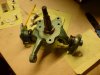
I am having some issues with a floaty feeling at the front end when going in a straight line, once turned into a corner everything feels like you are on rails which is great! I am using Mk2 Granada (U.K.) front uprights and fabricated wishbones, just wondering if anybody else out there has used these parts and perhaps has details of the geometry they could share.
 

Howard Jones

Supporter
Could be a dead shock.......but I agree with Niel, check your suspension setup. Especially toe. To clarify, when you say in a straight line, what speed? 40- 70mph or higher and close to or exceeding 100mph? And in a turn, light legal speed turn, or highly loaded aggressive cornering? Both directions?
 

Mike Pass

Supporter
GTD settings from build manual

Tyre pressure F 21psi R 23psi (Front 215.60X15 Rear 275/55X15 Avon cr6zz)
Toe in F1.6 – 3.2mm R 0 -1.6mm
Camber F 15 min neg R 30min neg
Caster F 3deg 20min

Other points
Check the shocks are OK and the adjustment is working
Check the suspension bushes as they are rubber and can fail. Replace with polybushes.
Check anti roll bar bushes and drop links.
Check top and bottom balljoints for play.
Remove shocks and check the suspension is moving freely.
A deep front nostril helps with stability at speed.
Ground clearance chassis to ground Front 4" Rear 4.5"
Cheers
Mike
 

Dave Bilyk

Dave Bilyk
Supporter
Hi David, I have the same uprights and your description matches my experience. I'm not sure if you just left out the shoulder wrenching effort required to do a 3 point turn. The other thing I've noticed is that on track on sweeping high speed corners it gets quite heavy again. If you have all those it's the overall geometry rather than the setup, but all the advice already given by Mike Neil and Howard too. I would love to fit a different solution that corrects these faults. I would take advice on it, but there seem to be 3 fundamental issues 1 A large scrub radius / low King Pin Inclination 2 A small Ackerman effect 3 Little camber gain. Possibly the only setup change that might help would be to increase negative camber which I can't as mine isn't adjustable. Mine is a DAX40 but does use the GTD parts as far as I can see.
 

Attachments

  • DSC00024.JPG
    DSC00024.JPG
    244.5 KB · Views: 359
They look like the Ford TD and TC Cortina uprights, or at least very similar.

TC TD MK3 CORTINA GENUINE FORD NOS L/H FRONT WHEEL SPINDLE | eBay

if so these are quite commonly used in a number of other kit/component cars. As I understand it, the wheel bearings are a common size and it is possible to attach different hubs, with either the same or different PCD's. One of the local clubman builders here where I am, the late Graham Lewis, being the genius machinist, engineer and gentleman that he was, went down the path of making new replacement hubs, that not only significantly reduced the weight but also got the scrub radius down to practically zero. He went to a single sided sliding caliper to reduce the distance between the disc face and the back of the wheel spokes, located a suitable rotor that he could mount up to clear the lot and then machined up an alloy hub that moved the stud face as far inwards as he could get them.

he also went to the trouble of calculating and measuring the KPI by mounting the spindle up in a live center on the lathe via the axle and then using the tool post and the graduations on the lathe worked out the coordinates for the ball joints. Think it was a very respectable 4° KPI. I wish he was still here today so I could bounce ideas off him.

RIP TDC.... aka Graham Lewis.
 
David (B) and Ryan, the uprights I''m using on mine are from a Cortina and look identical to the photo shown. When I was originally sourcing mine many years ago (from a Dutch breakers yard) I was keen to know the KPI (or rather SAI ). I made up a jig and turned down a long steel rod to fit snugly through the upper and lower ball joint holes. I measured an angle of 6.1 degs. More recently, I took my car to an alignment shop and they measured a value of 6.0 degrees. I have seen a KPI /SAI angle of 4 deg quoted previously for the Cortina upright in other forums, so am sure that is also correct. This leads me to wonder if there were perhaps small differences between UK and German/Belgium manufactured Cortinas. Can't remember for sure but it was LHD and maybe made in Ghent. If that is the case, the higher KPI/SAI could lead to reduced scrub radius and low speed steering weight - although 2 degrees won't have that much effect. My scrub radius is about 90mm. I also recently increased my front-end castor from about 2.5 degrees to 5 deg which improved the steering self-centering.
 
Trevor, im in Australia, so it might be something that Ford Australia made up. I haven’t had a set at my disposal for a while so can’t remember. I seem to recall that the ball joint tapers were at different angles, so adjusting the height of the ball joint also altered the KPI. Not that it’s possible with standard Ford ball joints, but if you went to a rod end or rose joint on the top with spacers you could certainly raise the pick up and decrease the SIA.
 
Thanks for all the ideas guys, I have been a bit remiss and not looked at the site for over a month! The floaty feel is only in a straight line, once turned in all feels good. No suspension play in upright ball joints or any rose joints (no bushes) all parts are new. I don't think it is as simple as the toe setting, I have done a lot of reading recently as my knowledge is starting from a point close to zero. I built a bump steer gauge and this seems to be the problem, 7mm change on full spring compression range and more than that on extension! Looks like I need new geometry - wishbone making take 3 and steering rack making take 2!
 

Mike Pass

Supporter
Bump steer is a common issue on GTDs which use the same uprights. The standard fix is to raise the steering rack by using steel blocks. I can't remember offhand how thick the blocks are but I will check. Whilst it is impossible to entirely remove all bump steer it can certainly be reduced to being unnoticeable especially over the usual range of suspension movement in normal driving. I would use a cheap laser pointer attached to the hub set horizontally, after removing wheels and coilovers, use a jack to move the suspension up and down. Aim the laser dot at a wall or large card and mark the red dot positions as the suspension is cranked up and down. The idea is to get the line of dots to be a vertical straight line.
My GTD has the rack raised and does not have bumpsteer issues.
Cheers
Mike
 
Mike, usual rack raise on standard GTD was always 5/8 inch ( 16mm ) . The geometry on the Cortina upright is no good for the GTD, the standard was always mk3/4 cortina, but even these require modification to the standard geometry settings to get close. Cast aluminium uprights that can accommodate great KPI and caster angles, together with adjustable steering arms, transform the car,
 

Mike Pass

Supporter
Thanks Frank - I had forgotten. Agreed the John Wisher uprights are excellent and the best way to go. Unfortunately the cost is quite high (see SGT website) and you also need to buy new knock on wheels.
There are some cheaper ways to get better geometry such as the Granada Mk3 uprights with "mushrooms" in the strut sockets. Or the Willwood Mustang 2 spindles (standard or 2" drop) which are strong and have some good cheap brake upgrades available. However both these options will require new wishbones.
I guess it depends on what you want to do with the car and how deep your pockets are!
Cheers
Mike
 
I have also got my own front upright castings, with sufficient extension for the top swivel bearing to enable the KPI to be designed to go with the other geometric decisions, I use a lot more caster than most, but one thing I dont get is understeer ! Frank
 
I supplied The original uprights that Richard Guest modified to make patterns for the castings that John Wisher used to make his uprights. Out of the deal I received a pair of blank castings which I haven`t been able to get machined yet. The castings I supplied were Gardner Douglas like the ones that failed on Malcom`s GTD hence being beefed up by Richard.
 

Mike Pass

Supporter
Thanks Kev. I didn't know that. You are a mine of historical info. Maybe John can machine them up for you.
My info is that the GTD front uprights were Ford Granada Mk2. The rear uprights are fabricated to take Ford Granada Mk3 hubs. I assume this to be correct as I replaced my front and rear bearings and this is what I used.The front bearings have to be set for the correct amount of play by tightening and then backing off a quarter turn. The rear Granada Mk3 bearings have to be tightened to at least 200 ft.lbs. On the GTD they are handed so check the thread direction. I use a huge 3/4" torque wrench for this with I think a 41mm socket. The nuts are a type of nylon so need new ones each time. I believe the standard Tornado set up is the same.
The front uprights can be changed to Granada Mk3 but as the Mk3 uses McPherson struts they need an adaptor (mushroom) fitted in the strut socket which has been drilled/ taper reamed to take the GTD taper top joint.
Cheers
Mike
 
Thanks for all the thoughts. Mike, my first attempt at bump steer measurement was along this lines of what you describe, the problem with this method is that you do not take into account the fact that the hub is moving in an arc as the wishbones move through the suspension travel so if you get the laser dots all vertical it actually means you have introduced bump steer. My new setup for measuring takes the arc of movement into account so it should work much better.
 
Back
Top