Homebuilt Mid-Engine Sports Racer

Neil

Supporter
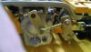
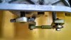
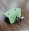
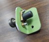
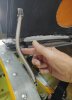
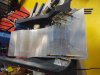
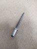
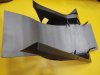
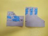
OK, Howard, here are two more pictures. I formed the toe loop out of 0.040" 5052 H34 aluminum. To make the shape a bit stiffer, I formed two slight flanges on each edge. It's riveted to the top of the pedal. To be perfectly frank, I find it a PITA and I wouldn't have added it if it were not required by the SCTA rule book.
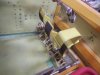
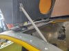
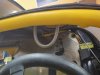
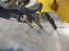
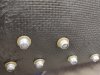
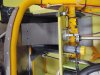
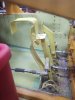
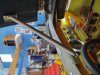
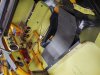
Lots of dirt and salt to be cleaned out.
 

Attachments

  • IMG_20210613_085824705.jpg
    IMG_20210613_085824705.jpg
    313.9 KB · Views: 331
  • IMG_20210613_085839534.jpg
    IMG_20210613_085839534.jpg
    183.2 KB · Views: 332

Howard Jones

Supporter
Hummm......................good idea from a stuck throttle safety perspective but I think it would be a nuisance unless I got used to it. Maybe I could add one that I can remove if I don't like it. One problem for me is to get the peddle assembly out to do it is kinda a job best left for tomorrow if you get my drift.
 

Neil

Supporter
Yes, this SCTA requirement is for a stuck throttle... although with a cable linkage it would do no good at all. There isn't much room around my pedals and it just gets in the way.
 

Terry Oxandale

Skinny Man
My throttle cable runs along the coolant lines and into the engine bay. I can remove the seat-back to get to the front of the engine very easily, but one day I inadvertently allowed the cable to get crimped behind the seat-back and framing when I was re-inserting the seat-back, which resulted a stuck throttle once pushed. Fortunately, I had a similar device (it comes in from the side and over the foot rather than over the toes), and was able to quickly drop the RPM to a safe level. Never know when a safety device becomes a necessity.
 

Neil

Supporter
I've been considering something to hold my driver's side door in the raised position after I manually push it open. I have a support rod that can hold it open but I can't raise it from the driver's seat, only from the outside. Initially I thought about using a gas spring and may try one yet but I found another way to do the job.

A straight helical-wound spring has lots of stiffness in compression but if it is pushed sideways, it collapses rather easily. Some clever individual seized upon this principle to create a purely mechanical hold-open. I ordered an all-stainless spring assembly from a marine hardware company for about $20 and gave it a try. I had to remove the lower end attachment for my application and make a bracket that would fit without interference. I had a piece of 3/4" aluminum angle and mounted a floating nut plate in one leg to receive a 10-32 oddball fastener I had. This fastener fits through the lower spring loop end. Both end attachments are riveted in place, as is the nut plate. The nut plate needed small diameter rivets (a #40 hole) and I had a bag of that size Cherry rivets. They were slightly too long a grip length but since they only held the nut plate in place, I would go ahead and use them. The upper end uses 3/16" rivets into the door.

The spring holds the door up nicely and when I push the spring sideways slightly, it goes down. On the downside, the placement results in the curved spring hanging down further than I'd like. I may move it to the rear edge of the door if it won't interfere with my helmet.

One thing more- when working on fabricated parts, de-burr all holes and break sharp edges (this is just basic metalwork) but I recommend also radiusing all those square corners. The corners add no strength but they do add weight and they lie in wait for the unwary. If you've never gashed yourself on a sharp corner when working on your car, it's only a matter of time before you do. Use a belt sander to round off the corners and then break the edges with a file. It looks better, too.
 

Attachments

  • IMG_20210706_101752087.jpg
    IMG_20210706_101752087.jpg
    324.3 KB · Views: 230
  • IMG_20210706_102428488.jpg
    IMG_20210706_102428488.jpg
    296.1 KB · Views: 220
  • IMG_20210706_102450791.jpg
    IMG_20210706_102450791.jpg
    360.5 KB · Views: 216
  • IMG_20210706_112917919.jpg
    IMG_20210706_112917919.jpg
    279.5 KB · Views: 215
  • IMG_20210706_112933228.jpg
    IMG_20210706_112933228.jpg
    325.8 KB · Views: 219
  • IMG_20210706_113037853.jpg
    IMG_20210706_113037853.jpg
    222.1 KB · Views: 219
  • IMG_20210706_113957764.jpg
    IMG_20210706_113957764.jpg
    168.3 KB · Views: 243

Neil

Supporter
It looks like the only way I'm going to scrunch down far enough to get my larger new helmet far enough below the roll cage to pass tech is to remove a brace so that I can get my left knee bent up a little higher. Unfortunately, I have a sheet of 6Al4V titanium riveted in place there. The Ti needs to be cut so that I can cut the tubing brace so I set about that today.

The first thing I tried was a 3" Harbor Freight cut-off wheel. Two abrasive discs resulted in about a 2" cut and the HF motor died. :mad:

Next, I hauled out my DeWalt angle grinder with a 4.5" metal-cutting diamond blade and I'm 95% finished with that cut. Lesson: sometimes you can get away with buying cheap $hit but not very often.

:rolleyes:

These are REALLY good!
 

Neil

Supporter
Randy, this is located in a place that doesn't lend itself to plasma cutting or I'd gladly do that.

Scott, thanks for that link. Those discs look really good but I wish they came in less than packs of 100.
 

Neil

Supporter
I needed to get my helmet lower in my roll cage ( the reason for cutting a tube and a panel) and now I can sit lower and further forward but my seat needs to be re-built. I'm in the middle of that task right now. I'm fabricating the new seat back and bottom from 0.125" 5052 H32 aluminum with attachment tabs of 3003-H14. The various pieces will be riveted together with 3/16" AVEX rivets. Thank goodness for cylindrical Cleco fasteners! I'm using an "Armstrong" bender (bending the large piece by hand and the tab bends are hammered over a piece of 1 7/8" scrap steel tubing) and the surfaces are scuffed with a yellow 3M bristle disc to provide some "tooth" for a coat of "Steel-It" polyurethane. Allen Grant, the owner of the Lola Mk 6GT, recommended this stuff.
 

Attachments

  • IMG_20210821_115036874.jpg
    IMG_20210821_115036874.jpg
    356.8 KB · Views: 175
  • IMG_20210821_115046562.jpg
    IMG_20210821_115046562.jpg
    363.4 KB · Views: 175
  • IMG_20210821_120049930.jpg
    IMG_20210821_120049930.jpg
    313.5 KB · Views: 174
  • IMG_20210821_120057179.jpg
    IMG_20210821_120057179.jpg
    329.7 KB · Views: 197

Neil

Supporter
More progress on my new seat. It is actually a modification of my original fiberglass tub that fits down inside the chassis tubes. The 0.125" aluminum seat back is finished and painted gray polyurethane. This resin contains fine particles of 316L stainless steel, a rather unusual "spray paint". I've finished 3 of the 4 brackets to secure the large aluminum seat back to the fiberglass tub, finished those in black polyurethane and riveted the parts together with 3/16" AVEX rivets. Since the fiberglass has limited pull-through strength, I added #10 AN steel flat washers as back-up to the rivets. These provide a larger area and increase the pull-through strength considerably.

The rectangular holes in the sides are for my lap belt. I have a 7-point harness from DJ safety.

BTW, I found that "Ram Board" is a wonderful material for making templates. This is a tough fiber-like material that is laid on a floor to protect it when moving furniture and appliances through a house. It's cheap, about $22 a roll, and can be cut with large scissors. I noticed that it bends more easily in one direction than another so take advantage of that when making a non-flat template.
 

Attachments

  • Seat 4.jpg
    Seat 4.jpg
    104 KB · Views: 154
  • Seat 5.jpg
    Seat 5.jpg
    154.5 KB · Views: 148
  • AVEX 1.jpg
    AVEX 1.jpg
    199 KB · Views: 154
  • Seat 1.jpg
    Seat 1.jpg
    74.9 KB · Views: 158
  • Seat 2.jpg
    Seat 2.jpg
    122.4 KB · Views: 149
  • Seat 4.jpg
    Seat 4.jpg
    104 KB · Views: 147
  • Seat 5.jpg
    Seat 5.jpg
    154.5 KB · Views: 144
  • Seat 6.jpg
    Seat 6.jpg
    94 KB · Views: 144
  • Seat 7.jpg
    Seat 7.jpg
    246.8 KB · Views: 165

Neil

Supporter
OK, I finished my new seat this afternoon and tried a trial fit into the chassis. I'll need to trim a bit from the edges but it looks promising. I put it on a scale and it weighs 13 lbs. Photos will be forthcoming.
 

Neil

Supporter
Two bolts for my safety harness crotch straps still need to be added before I'm finished but I did a "trial fit" and I think it looks OK and it gets my helmet lower in the car which was the whole reason for this exercise.

The first photo is looking down through what would be the windshield but I removed the front body section to get access to everything. The second is through the driver's side door. As you can tell, I'm a fan of zinc chromate on aluminum panels.
 

Attachments

  • Seat 8.jpg
    Seat 8.jpg
    312 KB · Views: 166
  • Seat 9.jpg
    Seat 9.jpg
    343.6 KB · Views: 166

Howard Jones

Supporter
Neil, I have been collecting pictures of rod shifters in mid-engined cars with G50s. I like the simplicity of the gear shift system at the cockpit end. Could you post a gearbox end shift rod arm attachment picture also?

I built a similar seat for my GT40 for track days out of aluminium to make room for my helmet. It is interesting just how little 'seat" is necessary for a race car. Tightly belted in like you are in a race seat requires little or no padding. Your body is actually the padding and the less it can move the more comfortable it actually is as long as the surfaces are smooth. Did you consider a head "halo". I made one up out of cardboard for my SLC but there is very limited room and it severely limits access so I put it aside for now. I would be interested in your thoughts on implementing what is clearly a good idea.

I can't wait to see you run that car in full anger. 200MPH club here you come.....................
 

Neil

Supporter
Howard, the SCTA requires less than 1/2"of padding on a seat so I'll leave it off and run completely bare aluminum. No flammable upholstery that way either.

I've attached photos of my rear G50 shift linkage. In the system there is a short link to reverse the rod rotation. it is made up of odds & ends, in this case a spherical rod end bearing on one end and a ball bearing on the other. :)

The rod is 3/4" Thompson Case 60 ground & polished steel running in Thompson polymer bearings. The rod surface is extremely hard, 60 Rockwell C, so it is necessary to grind away a divot to keep set screws from slipping or for drilling a hole for a u-joint bolt. I posted a photo of the divot earlier.

Since I'm still getting my car checked out, I've entered the "150 Club" event in a couple of weeks at Bonneville. In this event, I'm limited to 159.999 mph or I'll be disqualified. If everything feels OK on these runs, I'll enter my class, B/GMS (B/gas modified sports) next year. This car is geared for 209 mph @ 7200 rpm.

Hell, just driving a car on the salt of Bonneville that I designed and built myself is reward enough, whatever its speed.
Like Burt Munro (Anthony Hopkins) said at the end of the movie "The World's Fastest Indian",

"I did it!".
 

Attachments

  • Shift linkage G50  Newest 1.jpg
    Shift linkage G50 Newest 1.jpg
    143.4 KB · Views: 163
  • Shift linkage G50  Newest 2.jpg
    Shift linkage G50 Newest 2.jpg
    138.2 KB · Views: 150
  • Shift linkage G50  Newest 3.jpg
    Shift linkage G50 Newest 3.jpg
    202.8 KB · Views: 140
  • Shift linkage G50  Newest 4.jpg
    Shift linkage G50 Newest 4.jpg
    171.6 KB · Views: 130
  • Shift linkage G50  Newest 5.jpg
    Shift linkage G50 Newest 5.jpg
    97.8 KB · Views: 132

Howard Jones

Supporter
That's the cleanest method I've seen so far. Is your G50 flipped GT40 style or is the R&P reversed? Is that why you changed direction with the small link?

I can't wait to see the inboard video someday. Developing a homemade race car is really hard. Believe me I know. Things go wrong that would never happen to a streetcar and you can't foresee them until they do. It's the ultimate wack a mole process!
 
Back
Top