Jack, here's tonight's offering...
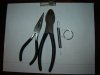
Tools:
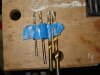
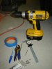
5/16” and two smaller drill bits
Electric variable speed hand drill
Workmate bench as a vice
3/8” X 16 Tap (Craftsman)
10mm hex head socket 3/8” drive
3/8” ratchet with 3” extension
1 7/16” socket 1/2” drive
½“ drive ratchet
Penetrating oil
Greenlee multi-sized drill bit.
Appropriate sized open end wrenches
Allen wrench
Rotary tool and grinder tip
Supplies:
Four 3/8 - 16 X 1” stainless steel hex head cap screws
Four 3/8 stainless steel washers
Wilwood parking brakes (RCR supplied)
Brake caliper mounting brackets (RCR supplied)
Painters tape
Hand brake assembly (RCR supplied)
Stainless steel button head screws for the mounting frame and attaching the handle (two 5/16th x ¾ inch and four ¼ X ¾)
Procedure:
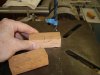
1. Follow the instructions in the RCR build manual. I used tape on the drill bits as a marker set at 1 inch depth to know when to stop drilling.
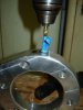
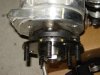
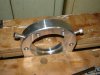
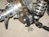
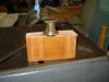
2. Exception: The brake caliper spacer had too small bolt holes which I drilled out on the drill press and polished for better presentation.
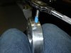
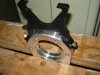
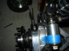
3. Second exception, I will need to purchase four more caliper bolts for the spacers. The originals are slightly too short with the new spacers in place on the larger brake disc. The lock washers won’t fit comfortably on the bolts. Maybe Lok-tite will do the trick(?)
4. Test out brake lever action and adjust and pads with the adjustment bolt on the back allowing for good lock down and release of the caliper.
5. Secure the adjustment bolt with the locking nut against the back of the caliper.
6. Follow the RCR instructions for mounting the hand brake handle assembly.
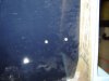
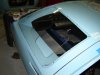
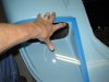
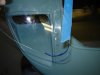
7. Drill the holes in the firewall and the back inboard part of the chassis where they exit to the parking brake calipers.
8. One hole in the mounting frame was not quite in line, the rotary tool and grinder tip were use to lengthen the forward hole on the mounting bracket to allow attachment of the brake handle to the bracket.
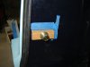
9. After assembly of the handle assembly and mounting bracket place it in the appropriate position spine tunnel and mark the floor for drilling the holes to attach the entire assembly to the floor.
10. Make sure the brake will engage correctly and can be adjusted to operate properly before bolting it to the floor.
11. Drill the attachment point holes as marked and attach the assembly.
12. Attach and tighten all the cable points as needed.
13. Do not over drill the holes for the cables as noted in the RCR build manual.
Time required: 7 hours. The time didn’t include rounding up the tap & die set (I don’t have one) and getting a 10mm hex head socket. That was another 2 hours of chasing around.
Total: 9 hours
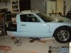
Parking Brake Calipers and Hand Brake Mounting
Tools:
5/16” and two smaller drill bits
Electric variable speed hand drill
Workmate bench as a vice
3/8” X 16 Tap (Craftsman)
10mm hex head socket 3/8” drive
3/8” ratchet with 3” extension
1 7/16” socket 1/2” drive
½“ drive ratchet
Penetrating oil
Greenlee multi-sized drill bit.
Appropriate sized open end wrenches
Allen wrench
Rotary tool and grinder tip
Supplies:
Four 3/8 - 16 X 1” stainless steel hex head cap screws
Four 3/8 stainless steel washers
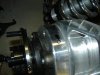
Wilwood parking brakes (RCR supplied)
Brake caliper mounting brackets (RCR supplied)
Painters tape
Hand brake assembly (RCR supplied)
Stainless steel button head screws for the mounting frame and attaching the handle (two 5/16th x ¾ inch and four ¼ X ¾)
Procedure:
1. Follow the instructions in the RCR build manual. I used tape on the drill bits as a marker set at 1 inch depth to know when to stop drilling.
2. Exception: The brake caliper spacer had too small bolt holes which I drilled out on the drill press and polished for better presentation.
3. Second exception, I will need to purchase four more caliper bolts for the spacers. The originals are slightly too short with the new spacers in place on the larger brake disc. The lock washers won’t fit comfortably on the bolts. Maybe Lok-tite will do the trick(?)
4. Test out brake lever action and adjust and pads with the adjustment bolt on the back allowing for good lock down and release of the caliper.
5. Secure the adjustment bolt with the locking nut against the back of the caliper.
6. Follow the RCR instructions for mounting the hand brake handle assembly.
7. Drill the holes in the firewall and the back inboard part of the chassis where they exit to the parking brake calipers.
8. One hole in the mounting frame was not quite in line, the rotary tool and grinder tip were use to lengthen the forward hole on the mounting bracket to allow attachment of the brake handle to the bracket.
9. After assembly of the handle assembly and mounting bracket place it in the appropriate position spine tunnel and mark the floor for drilling the holes to attach the entire assembly to the floor.
10. Make sure the brake will engage correctly and can be adjusted to operate properly before bolting it to the floor.
11. Drill the attachment point holes as marked and attach the assembly.
12. Attach and tighten all the cable points as needed.
13. Do not over drill the holes for the cables as noted in the RCR build manual.
Time required: 7 hours. The time didn’t include rounding up the tap & die set (I don’t have one) and getting a 10mm hex head socket. That was another 2 hours of chasing around.
Total: 9 hours