
You are using an out of date browser. It may not display this or other websites correctly.
You should upgrade or use an alternative browser.
You should upgrade or use an alternative browser.
J. Salmon RCR-40 Build
- Thread starter salmjo1
- Start date
Here you go!


John, I'm interested in 180-degree headers for an LS7. Could you please tell me what your primary lengths ended up being?
John, I'm interested in 180-degree headers for an LS7. Could you please tell me what your primary lengths ended up being?
Mark,
Fran did them custom while the car was at RCR. For the price I paid, you'd have thought they fell off the back of a truck.
There is variation in the primary length, they are roughly 30-40 inches. I am sure that would be a problem for some racers, but packaging is really tight for me, so I have zero complaints.
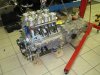
Front dress
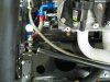
Got brackets and pulleys for my front components. I couldnot find anyone that made brackets for either in the location I wanted on an LS7. Other LS motors yes, but not mine. So I found Street and Performance: Welcome to Street and Performance
I shot a picture, told them what I wanted, and they custom fabricated pollished aluminum bits delivered to my door in about a week. I am using a C130 140 amp alternator, which will sit level with the AC compressor on the driver side. There is a single belt that runs in the outer crank pulley groove around both AC compressor and alternator, tensioned by the alternator. VERY slick! once I knew where everything was going to be, I began running all the front plumbing. I need a couple -12AN fittings and I will be done with that part.
I knew I would have to put cut-outs in at least the alternator side on the engine bay. I am going to do them on both sides. I plan to get the aluminum pieces that Fran makes for the Ford guys and modify them for use here. I have almost finished marking all the chassis holes I need, then I will pull the motor and begin cutting.
Attachments
Did what I had been dreading, rough fit of the dash. Nice and straight, I am verry happy to have that behind me. I have it cut so that the roll cage can be removed without unfastening the dash. You will have to remove the spider and the roll bar to get the dash out though. Hopefully I won't have to.
Attachments
J.
Glad to see someone else that is going the direct route with the water lines and doing away with the things on the front of the engine that get in the way. I am assuming you probably moved your engine/drive train forward as a result. What pump are you using and how have you got it plumed/wired/controlled.
Bill
Attachments
Bill, check out page 4, post #64 of my build log. I have a picture of the pump and how I plumbed it. Meziere actually recommended I run it without a thermostat, but Ron McCall put me on to an external in-line one for NASCAR use. I'll try to shoot a picture. It would scare me if I didn't know that Ron was already running it with the same pump. It seems crazy to have two -12AN lines running in and out of the motor with a single -6 bypass line when the thermostat is closed.
Last edited:
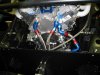
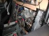
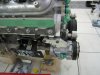
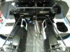
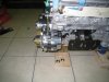
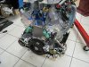
More work this weekend. The front of the motor is finally done. The "swingset" throtle linkage is mounted. We will trim down the moutning plate when we have a better feel for the throttle cable location. Took measurements off the compressor and alternator and cut corresponding holes out of the chassis. Plan to make an aluminum strut to stiffen the driver's side where I had to cut out the top corner of the box. Have cutouts for the swirl tank and oil tank done. Next step will be mounting the accessories (tanks, filters, valves etc) and getting the fuel tank plumbing done (in-tank pump mounts, sending units, etc)
Attachments
J,
Went back and looked at your earlier post on the thermostat setup. What I would really like is a pic of the hoses and the Y block arrangement on the engine with it out of the car. I am trying to make heads or tails out of it. The incar shot just doesn't do it justice. I am trying also to follow the routing(water flow path cold and hot) when all is hooked up. I had thought of using an external t'stat with my pump, but am having trouble visualizing. I right now will not use the thermostat, but rather a PWM type controller that is linear or so with the temp. It means slower warm up, but a small price to pay to avoid thermal shock. I have the post on most of the external setups. My problem is space, so I am trying to keep it simple.
Still in the final build up(read slow) stage, but getting ever so close.
Bill
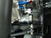
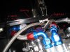
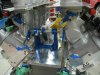
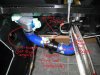
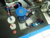
OK, here is a better picture of the in-line thermostat, with my skilled annotation. Motor is not in, so this is the best I have.
Two lines (covered in some heat wrap stuff) come out of the pump from the front. They go to the front of the motor. Out of the motor come two more -12 lines (not in place) which converge at the Y-block. Then into the thermostat, which has a -6 bypass. The bypass line (also not shown) goes back through the tunnel to the input line for the pump, bypassing the radiator. Once the T-stat opens, the flow is through the big line, to the radiator for cooling.
I hope this makes things easier to see.
Attachments
J,
Now I see it and it makes sense. Now all I have to do is decide if I want to add that extra braided hose and fittings. Will search for the thermostat and see how much that will set me back. With the equipment I already have I may stick with the no thermostat setup until later on. Otherwise I will have a BIG garage sale for the things I have been accumulating that I am not going to use!!
Bill
Fuel pumps
I have made an important transition. It has taken this long to realize that - unlike the Cobra where 4000 people had done it before - there are few people who have gone where this combo is leading me. I think I finally have gathered the nerve to break a wee bit of new ground.
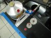
Running an EFI adds complexity, as has been discussed. Despite the nice internal baffles, I decided to plan for a lot of fuel sloshing and build a system that will reliably deliver fuel to the rails. The money I spent on the Kinsler intake is coming back now, as Earl at Kinsler is an amazingly patient teacher, and a true guru.
I have twin in-tank OEM style pumps with 45 micron pre-filters that feed into a vapor separation tank (also from Kinsler) as a swirl pot. From here, fuel is drawn by a more robust pump through a 25 micron filter, and pushed through a 10 micron filter to the rails. The fuel rails are plumbed in parallel, not sequence, which is a bit of a Kinsler thing. More on that after the motor is back in.
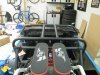
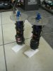
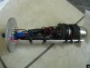
I could find no one that makes an off-the-shelf bracket for the in-tank pumps so that they would slide into a hole with a three inch plate. So I bought blank plates from Pegasus (special order, Fuel safe) and fabbed my own with some aluminum angle. I drilled the plates for the -6an bulkhead fitting and the electrical leads.
I cut teflon bushings to slip into the holes and used teflon washers to isolate the brass screws for the power leads and seal them. I was amazed at how little clearance there was. By the time I converted the -6an to a 5/16 hose (typical output on an OEM pump, but not on a race pump) I had about 2 mm to spare. The filter "foot" is a hair above the bottom of the tank. I had to splice the wires, and I was not sure about the longevity of my heat shrink tubing in gas (it did fine in a 3 day submersion test) so I ran the wires through short sections of fuel hose. That way, even if the heat shrink falls apart, the wires are both isolated.
I think the pumps look like home-made bombs. Let's hope they don't behave like that")
I am using the line on the fuel gauge sending units as my return line.
After doing a lot of reading, I changed from the standard tanks vents. I wanted as few lines as possible in the cabin, so I plugged the 1/8 NPT fittings by the filler hoses and added ball-valve roll-over fittings to the rear of the tanks. I used -8an valves. This should allow me to fill the tanks at regular pump speed instead of dribbling it in. Going on the advice of Fuel Safe, I will run a line up as high as I can go, make a loop like a pigtail, and then run it down below the bottom of the tank. That way, if the car does roll over, the end of the hose is above the tank. I have internal check valves for the low end of the hose. You want to be sure that nothing can obstruct this line. If you do not have a working vent, the pump will pull a vacuum and your fuel supply will stop.
I still have a few more things to do to get the chassis ready for the final motor install.
I have made an important transition. It has taken this long to realize that - unlike the Cobra where 4000 people had done it before - there are few people who have gone where this combo is leading me. I think I finally have gathered the nerve to break a wee bit of new ground.
Running an EFI adds complexity, as has been discussed. Despite the nice internal baffles, I decided to plan for a lot of fuel sloshing and build a system that will reliably deliver fuel to the rails. The money I spent on the Kinsler intake is coming back now, as Earl at Kinsler is an amazingly patient teacher, and a true guru.
I have twin in-tank OEM style pumps with 45 micron pre-filters that feed into a vapor separation tank (also from Kinsler) as a swirl pot. From here, fuel is drawn by a more robust pump through a 25 micron filter, and pushed through a 10 micron filter to the rails. The fuel rails are plumbed in parallel, not sequence, which is a bit of a Kinsler thing. More on that after the motor is back in.
I could find no one that makes an off-the-shelf bracket for the in-tank pumps so that they would slide into a hole with a three inch plate. So I bought blank plates from Pegasus (special order, Fuel safe) and fabbed my own with some aluminum angle. I drilled the plates for the -6an bulkhead fitting and the electrical leads.
I cut teflon bushings to slip into the holes and used teflon washers to isolate the brass screws for the power leads and seal them. I was amazed at how little clearance there was. By the time I converted the -6an to a 5/16 hose (typical output on an OEM pump, but not on a race pump) I had about 2 mm to spare. The filter "foot" is a hair above the bottom of the tank. I had to splice the wires, and I was not sure about the longevity of my heat shrink tubing in gas (it did fine in a 3 day submersion test) so I ran the wires through short sections of fuel hose. That way, even if the heat shrink falls apart, the wires are both isolated.
I think the pumps look like home-made bombs. Let's hope they don't behave like that
I am using the line on the fuel gauge sending units as my return line.
After doing a lot of reading, I changed from the standard tanks vents. I wanted as few lines as possible in the cabin, so I plugged the 1/8 NPT fittings by the filler hoses and added ball-valve roll-over fittings to the rear of the tanks. I used -8an valves. This should allow me to fill the tanks at regular pump speed instead of dribbling it in. Going on the advice of Fuel Safe, I will run a line up as high as I can go, make a loop like a pigtail, and then run it down below the bottom of the tank. That way, if the car does roll over, the end of the hose is above the tank. I have internal check valves for the low end of the hose. You want to be sure that nothing can obstruct this line. If you do not have a working vent, the pump will pull a vacuum and your fuel supply will stop.
I still have a few more things to do to get the chassis ready for the final motor install.
Attachments
Last edited:
Well done Jay. She's gonna be a monster!!!!
Re: making a bomb / bare wires etc..
Years ago I took apart my first in-tank electric fuel pump that had failed. I just wanted to see why it failed and how they worked in the first place. It failed because the sock got a hole rubbed in it from the tank and it sucked in a bit of trash from the tank and stopped the pump from turning. I continued my excursion as long as I had it apart.. Hmm Okay a vane type pump, here's where it gets it's supply of fuel ummm.. Okay - where does it go from here to get to the other end of the pump motor to the output line? Kept pulling it apart. No way! The output fuel from the pump itself goes THROUGH the bloody motor!! Yes, around the brushes, commutator, spinning armature and all and to the other end where along side the bearing is an output line...
Un-friggen believable!!! My brain is running a million miles an hour now - thinking of a sparking set of brushes and commutator on an electric drill and all this gasoline!!!
But wait! Liquid gasoline does not burn - only vapors do..
But wait! What if I run out of gas and turn on the key to start the car?
Insert your thoughts here...
The output fuel from the pump itself goes THROUGH the bloody motor!! Yes, around the brushes, commutator, spinning armature and all and to the other end where along side the bearing is an output line...
Un-friggen believable!!! My brain is running a million miles an hour now - thinking of a sparking set of brushes and commutator on an electric drill and all this gasoline!!!
But wait! Liquid gasoline does not burn - only vapors do..
But wait! What if I run out of gas and turn on the key to start the car?
Insert your thoughts here...
Because the fuel is used to cool the motor and prevent overheating failure! Often in-tank pumps are "fryed" when the tank is run out of fuel and the pump overheats rather quickly.
I have never heard of an in-tank pump exploding in an empty tank. I think the major manufacturers are pretty confident that they will not be blowing customers up!
Last edited:
Because the fuel is used to cool the motor and prevent overheating failure! Often in-tank pumps are "fryed" when the tank is run out of fuel and the pump overheats rather quickly.
I have never heard of an in-tank pump exploding in an empty tank. I think the major manufacturers are pretty confident that they will not be blowing customers up!
Precisely..
As I said - this was many years ago (talking about the 70's here)...
My point was in regard to the concern of bare wires that are inside the fuel tank. These concerns are unfounded due to the way the process of the fuel pump itself works, the exposed conductors wires and components..
Also - (without hijacking too terribly bad) I fee one of the key reasons of early fuel pump failure is not just running out of fuel but running below 1/4 tank for extended periods. This exposes the body of the fuel pump to air rather than the fuel to which it can exchange it's heat/cooling by..
No question it seems scary. I agree with all of the above about pump failure. Running them dry is just not a good thing.
My wiring concerns (once I became confident they were not going to explode) were more about shorting out. I have splices in the lines. At first, the heat shrink tubing was covering these areas, but the wires were running together. So, if the tubing cracked or came off for any reason, the exposed wires would short out the circuit. The way I ran them now, I could have left the heat shrink off, as each wire runs in its own conduit of 5/16 fuel hose.
My wiring concerns (once I became confident they were not going to explode) were more about shorting out. I have splices in the lines. At first, the heat shrink tubing was covering these areas, but the wires were running together. So, if the tubing cracked or came off for any reason, the exposed wires would short out the circuit. The way I ran them now, I could have left the heat shrink off, as each wire runs in its own conduit of 5/16 fuel hose.
Similar threads
- Replies
- 14
- Views
- 5K
- Replies
- 1
- Views
- 450