J. Salmon RCR-40 Build

Waiting and Updating

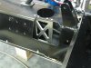
Well, I am somewhat stalled out. I really want to get the motor in, but I need two things: chassis stiffening brackets (at the water jet cutters, hopefully done this week) and hard lines from Hot Rod Air.

I decided to swap to hard lines in the center tunnel, so I am having HRA make them up. I think it is worth noting that I ordered (and paid for them) on March 2. I was told they would take three or four days to make. I still do not have them, now April 8. Hey Fran, does this sound familiar? Anyone who doubts that HRA has been slow to deliver parts to RCR should order something directly from them, you know, just for the experience. They are also supposed to be here this week. Fingers crossed.

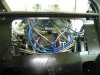
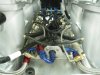
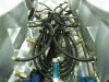
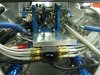
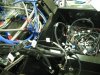
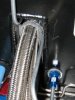
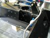
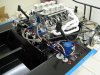
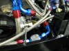
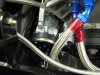
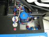
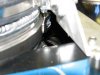
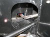
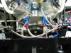
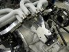
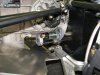
In the meantime, I completely re-did all the plumbing in the center. After reading Bill D's comments about heat, I decided that now was the best time to do a little more insulating. I pulled the thin stuff I had wrapped around the lines and wrapped all 5 of my coolant lines with much thicker thermal wrap. In was a PITA to get them through, but in the long run I think it will be worth it. The best solution would be to duct outside air through the tunnel so that the heat could be pushed into the engine bay instead of in the cabin. I am going to look at this, but I think residual space will be minimal when I am done, so it may not be effective.

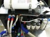
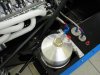
I also redid the flimsy aluminum line for the fire suppression system. I did not like that you could bend it easily by hand, and I was not happy with the path I had originally chosen. Any frontal impact would probably have rendered mine useless. This is run better and is much sturdier.

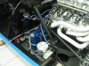
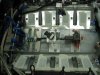
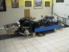
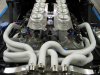
The radiator wll have to come off to get the hard lines through, but I will have to remove it to do a nice fan bracket anyway. I hope to pull it this week.
 

Attachments

  • Heat wrap.jpg
    Heat wrap.jpg
    31.6 KB · Views: 638
  • Steel FSS line.jpg
    Steel FSS line.jpg
    45.3 KB · Views: 755
Got my daughters involved. My oldest (10 this month) painted the exposed areas on my AC and alternator chassis holes black. Meanwhile, my 6 year old removed my radiator, with very little help. Once you put her on a job, she will not quit and refuses help!

Got the brackets for chassis reinforcement back from the waterjetter today and could not wait to get it rough fitted. Need to fit the other side, then both will be painted black and installed permanently. 4 bolts in the top and bottom, and three bolts from the back through the internal baffle. She's in there pretty dern snug.
 

Attachments

  • chassis bracket.jpg
    chassis bracket.jpg
    39.5 KB · Views: 777
Proof of concept

Fran felt the chassis did not need stiffening on the compressor side where the radius was not lost, and recommended that I use the shorter brace I had made for that side to complete the reinforcement of the driver side.

I finally got the hard lines from Hot Rod Air. It took two of us a couple of hours to get everything insulated and pushed through the tunnel. But I am happy with the results and feel it was worth the extra effort.

With the chassis prepped and the tunnel addressed, it was time for the moment of truth. To this point, I had measured the position of everything using the motor mounts as reference points. But I was not at all sure it was going to fit.

In fact, it fit PERFECTLY. It dropped right in. The spacers for the adapter plate, perfect. I will say it is SNUG! With all the plumbing in place, it is a hard to even show the alternator. It is obvious that alternator or compressor failures will be "engine out" replacements.
 

Attachments

  • Chassis brace.jpg
    Chassis brace.jpg
    42.2 KB · Views: 654
  • In1.jpg
    In1.jpg
    40.3 KB · Views: 781
  • In2.jpg
    In2.jpg
    53.8 KB · Views: 830
  • Alternator.jpg
    Alternator.jpg
    53.7 KB · Views: 657
  • Compressor.jpg
    Compressor.jpg
    47.8 KB · Views: 625
Putting the motor in went so smooth, I kept the momentum and plumbed everything I could with the parts I had. I fabbed simple brackets to mount the solenoid valve (that selects the return flow to the tank that is active) and the fuel pressure regulator.

The oil lines also fit, another bit I was unsure would work. I plan to sleeve the lines where they run through openings to protect them.
 

Attachments

  • Fuel pumps.jpg
    Fuel pumps.jpg
    46.2 KB · Views: 581
  • Rear plumbing.jpg
    Rear plumbing.jpg
    47.8 KB · Views: 655
  • Oil tank.jpg
    Oil tank.jpg
    41.1 KB · Views: 557
  • Oil in.jpg
    Oil in.jpg
    27.2 KB · Views: 511
  • Oil out.jpg
    Oil out.jpg
    38.4 KB · Views: 580
A few other pics. Starter fits without modificatoin. Another picture of the front plumbing. And the rough draft of the secondary transmission mount.
 

Attachments

  • Starter.jpg
    Starter.jpg
    45.6 KB · Views: 570
  • Front plumbing.jpg
    Front plumbing.jpg
    53.9 KB · Views: 678
  • Tranny mount.jpg
    Tranny mount.jpg
    49.5 KB · Views: 684

Randy V

Moderator-Admin
Staff member
Admin
Lifetime Supporter
Fantastic progress... The plumbing looks like you spent a good deal of time planning and finally execution.

The engine looks great! 8 magnificent stacks! Wishing there was something that could be done with those ignition coil packs though.. They sort of take away some of the appeal for me...

Your shop looks way too clean... Put me in there a couple of days and I'd have it whipped into shape!!! :shocked:
 
Beautiful work J and nice progress. I'm with Randy, put me in there doing bodywork and that garage will never be the same! Maybe thats why you outsourced the dirty stuff? I'm closing in on pulling molds off my fender designs - it has been a really cool although time consuming learning experience and I'll sure be glad when my shop is clean again.

Your car is going to be sweet.
 
Still plumbing, but almost done. I am missing 5 fittings, and they will be here tomorrow.
Mounted the coolant overflow tanks and the oil catch can. The front of the motor looks busy, but I will line the hoses up neatly and secure them to the firewall. By sunday all liquid systems (fuel, oil, water) should be sealed. Then I go where I have never gone before. Wiring. Blah.

I also added an old tool to my garage that I have meaning to have available. It helps set the mood. Purchased in 1982, still rockin' out the hair metal :)
 

Attachments

  • final plumbing rear.jpg
    final plumbing rear.jpg
    53.2 KB · Views: 661
  • final plumbing front.jpg
    final plumbing front.jpg
    47.7 KB · Views: 622
  • oil and coolant catch tanks.jpg
    oil and coolant catch tanks.jpg
    53 KB · Views: 649
  • ax.jpg
    ax.jpg
    26.8 KB · Views: 652
The MAP sensor requires distribution to all 8 intake runners. Kinsler supplied a block for this. But the fuel pressure regulator takes reference off of the manifold pressure, so it needs to be connected too. I had a 2 x 2 x 1 inch piece of aluminum cut, and I machined a hole for the MAP sensor. I then tapped into each side with the apprioriate size holes and tapped them for the fittings. I then made an aluminum strap and bolted it all together. This block is mounted in the center of the valley, and you see it is hooked up to the distribution block and the pressure regulator. The valley plate is torqued, and I am ready to install the intake manifolds!
 

Attachments

  • MAP.jpg
    MAP.jpg
    33.3 KB · Views: 428
  • Map block.jpg
    Map block.jpg
    35.9 KB · Views: 394
  • Valley torqued.jpg
    Valley torqued.jpg
    45.8 KB · Views: 555
Organizing chaos

I got the intake manifolds installed. There are individual O-rings for each runner. To be organized in the valley are 8 stainless -3 lines for the IAC, 8 rubber lines for the MAP sensor distribution, a large plug and harness for the injector controllers, the throttle position sensor wire, and the fuel return line. And this is all stacked on top of the MAP sensor and its distribution block, and the fuel pressure regulator. And after several hours of fiddling and a few hundred zip ties, I got it where I liked it.

The block under the throttle linkage swingset is for the IAC. The motor is actually mounted in the passenger pontoon and connected to the block with the -8 line. The hose is actually the exit for the PCV valve. The IAC will apply the vacuum that the PCV valve needs to work, and the dirty air from the crankcase is recycled in the intake runners, as it would be on a modern car. It's all very clean, which is my primary goal. NOT :)

(in all seriousness, with modern EFI, the fuel efficiency and emissions should be respectable).

Unfortunately, I still have a big mess of lines and wires to sort.

But I do have an able helper in Boomer, our hyperactive greyhound.
 

Attachments

  • Rear view.jpg
    Rear view.jpg
    45.3 KB · Views: 608
  • Front view.jpg
    Front view.jpg
    48.9 KB · Views: 590
  • IAC block.jpg
    IAC block.jpg
    59.2 KB · Views: 590
  • Waiting mess.jpg
    Waiting mess.jpg
    65.5 KB · Views: 570
  • Santas little helper.jpg
    Santas little helper.jpg
    37.7 KB · Views: 512
Hi J.

With that amount wires and pipes runnig you could almost power a 3rd world village.
Is the controller also supplied from Kinsler ? Which one is it.
I´m thinking of putting a MEGASQUIRT system on my car later on ( with a custommade X crossover throttle system utilizing DUCATI 996 Throttle bodies).

TOM
 
Back
Top