Jason's Coyote Powered RCR40 Downunder

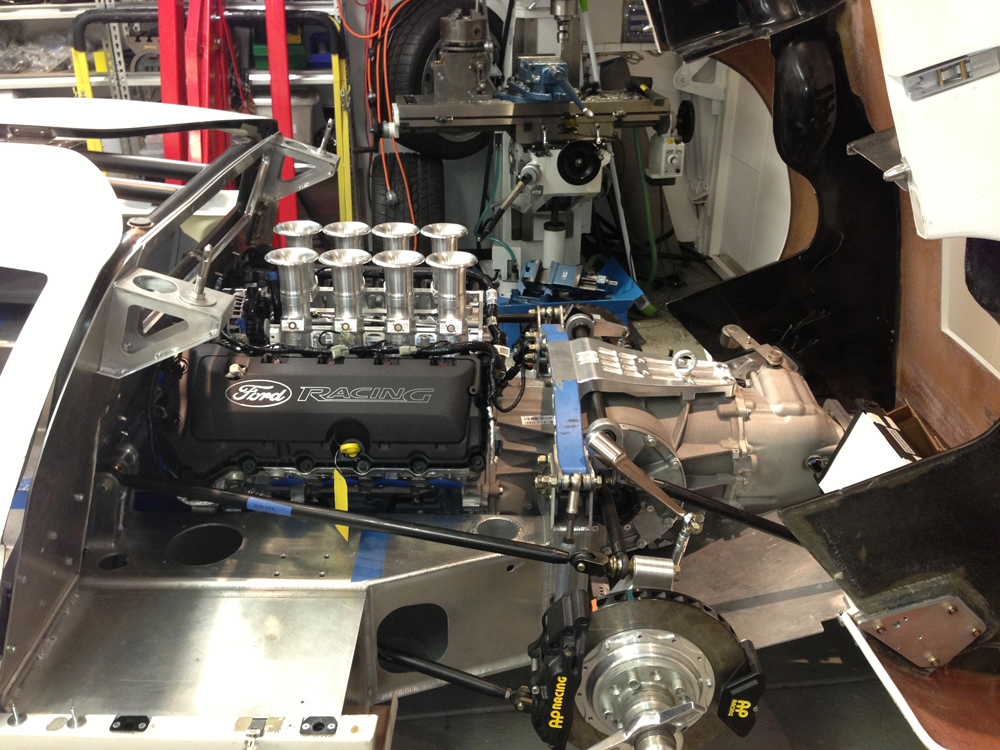
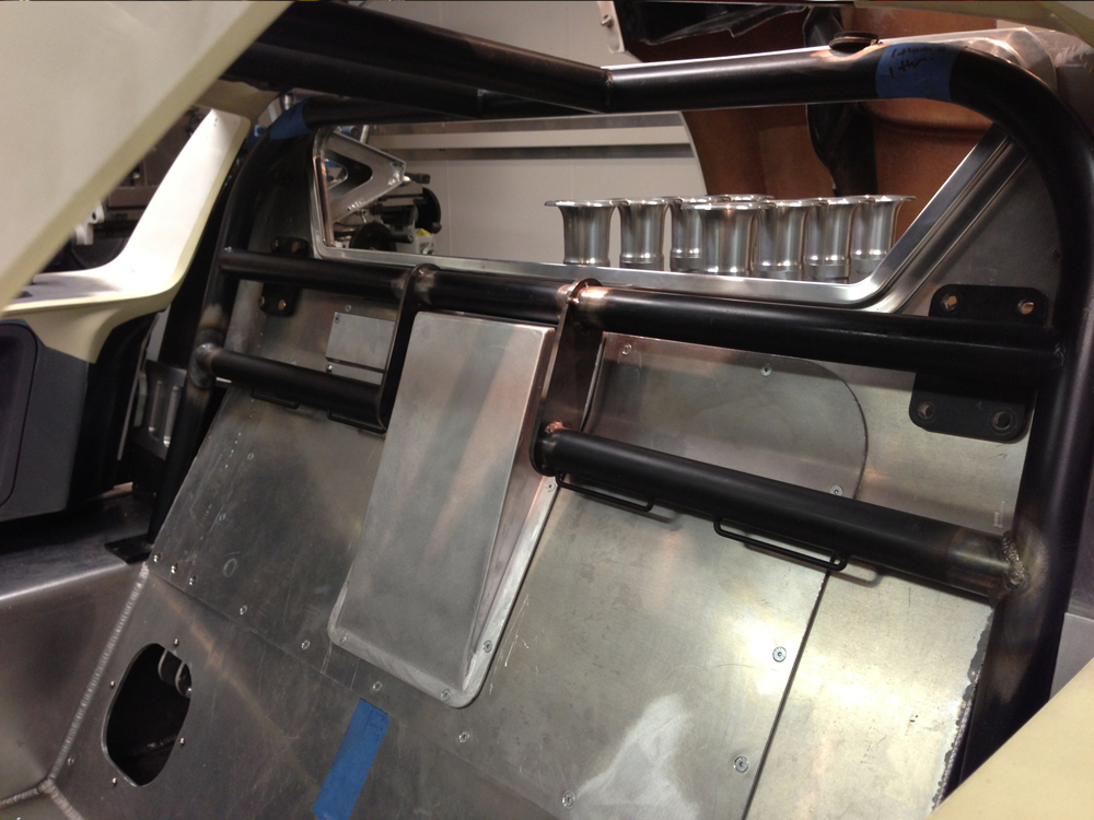
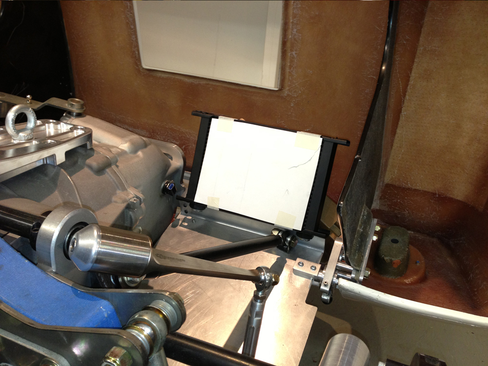
Hi Tom, I was going to look at adding them but they are really for serious racers and I can not drive to save myself! I think that when someone that knows how to drive helps me to tune the car I can just adjust them manually. Also finding room in the cabin for the adjusting levers is hard. Tom you may see another copy from your car below, I hope you don't mind? I also mocked up headers there is plenty of room (cross-over system with no catalytic converters and small mufflers).

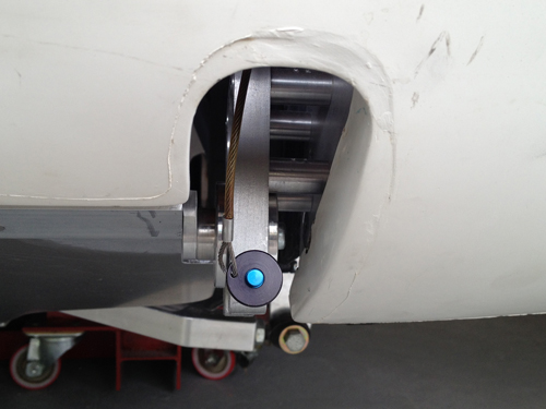
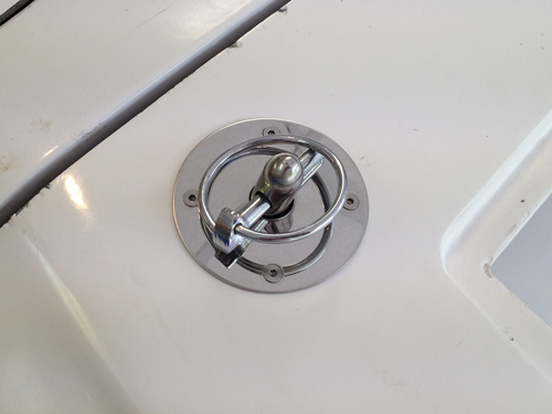
To make the removal of the rear clip easier I have made some rear mounts (shamelessly copied from other GT40's!). To remove the clip one just removes the Jergens quick release pin.

GT40-Rear-Clip-1.jpg


GT40-Rear-Clip-3.jpg


GT40-Rear-Clip-2.jpg


GT40-Rear-Clip-4.jpg


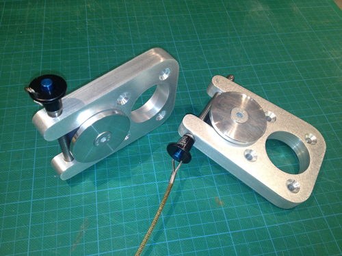
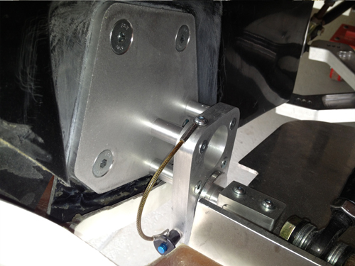
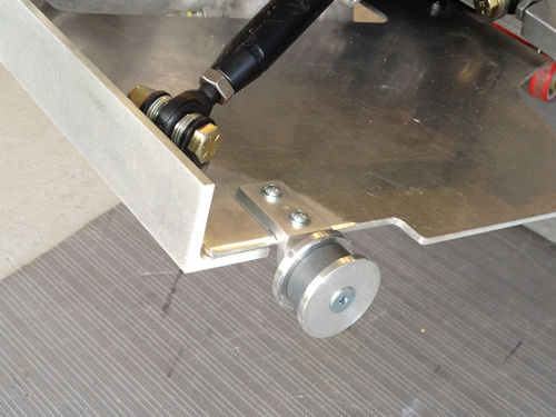
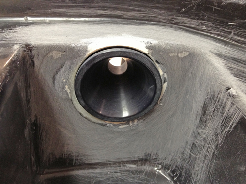
I also placed the hood pin caps on the body. To assist in closing without damage to the body I also bolted in nylon "pin guiding cones" under the clip. It allows me to just drop the clip into place and the cones ensure the pins guide easily into the neat holes.

GT40-Rear-Clip-5.jpg


GT40-Rear-Clip-6.jpg
 
Very nice work! Just an fyi, re: sway bar, the JBl cobra uses the blade type sway bar with electronic adjustment and LED indicator in the cockpit, something to peruse and very compact. The blades look the same size as the one you are using, I don't know how putting all the forces through one blade will work. If you cat walk or diagonally descend or ascend an incline (or curb) the blades should be flat, they will break I have heard.
 
Thanks Mark for the comments. Interesting point on the single blade breaking under that loading condition. I have seen single blade setups used a lot but I can understand the potential for that failure mode. I will see what happens, not scientific but not costly or dangerous either. If I need to put one on both sides I can as I have the same drop link geometry from side to side and can attach a flex blade onto the spline end of the bar (complex but do-able). Interesting on the electric adjustment, PM me if you have any links to some info. I love gadgets!
 
We have build a single blade setup on the 917 and also Fran is using them on his racecars. I think it all depends on the suspension travel involved and the cars geometry and therefore its tention to roll.

I´m also thinking about converting my setup to an cockpit adjustable blade setup.

The issue i´m facing is that i can not get datas on blade stiffness in the two most extreme adjustings ( vertical = strong ; horizontal = light) .
As i know that my setup is working it would like to get a blade which in the light position is giving me the same rate as my current fixxed arm setup at the lightes position. I contacted speedway engineering and asked for stiffness datas. I think in vertical position it is the same as a fixed arm, but due to them having different thickness blades the stiffness in horizontal position will be different. I asked them to give me the datas in percentage of the vertical position. (for example in horizontal position it is 50% as stiff as in vertical position for the 0,270" thick blade and 40% for the 0.200" blade). This would help me to define the blade needed to get a similar setup then my current ( just lighter with hollow bar and cockpit adjustable).
Did you get any datasheets with your blades?

BTW : have you seen what i have done for locating the hood pins in center
http://www.gt40s.com/forum/gt40-build-logs/24525-toms-rcr-40-trackracer-30.html#post374178


TOM
 
Last edited:
No data either Tom. You going to use two flex arms or one? I just purchased two different thickness blades at the longest length they sell and I expect that I may need to buy more to get it right! Currently have the 9.5" long Blade Arm .270" thick fitted. I went with a 1" diameter bar with a 1.25" wall thickness. Fairly thin as its fairly short in the car. I also have the drop links located inboard (no choice) so the travel is not huge, thus a fairly stiff bar and arm configuration.

Really could not get any advice and there are a lot of variables anyway. I will see how it goes, if I run out of adjustment I will have to change arms first and then maybe the bar to more compliant versions. Use the other parts on my next car!

Yes I saw your hood pin locators, very good. I will stick with mine until they get scratched up and I will turn and mill some up like yours. I want to get this thing on the road/track
 
Jason

No i would use one fixed and one adjustable blade arm as well.

The farer you have your droplinks located inboard on the suspension arms the softer the roll bar effect will be. The same bar with the same arms but droplinks located more outboard will be stiffer. Of course travel is less in the inboard location.

Don´t know if you have worked with the excel chart i provided on this forum for suspension calculation. Recommand to do it as an excercise, it will give you an pretty good idea where you at and what your resulting wheelrates of spring and swaybar are.
I don´t have it available here, but i again can attache it tonight.

TOM
 
Jason, here is their website with detailed information. to go any further you should contact the builder or designer, it is possible there are some type of propriety rights.

JBL home page

they do show 83# full flat with 1" deflection, and 1200# full firm with 1" deflection under detailed chassis data.

they are building a car now, i don't know if they are using electronic adjusters but it might be a good time to get ahold of them if they are having the electronic cards made.

they have pics of the manual adjusters on the website, here are the electronic version, the led's light up in relation to the adjustment of the blades. the switch below the led's are for front and rear, automatic release toggle style.
 

Attachments

  • adjusters 003.jpg
    adjusters 003.jpg
    60.9 KB · Views: 391
here is the formula for blade calculation provided by Mr. Hudgins.

Cantilever Beam Slope and Deflection Calculation for Load at Free End

Slope at free end = PL2 / 2EI
Deflection at any section = Px2(3L-x) / 6EI

Where,
P is the externally applied load,
E is the Elastic Modulus,
I is the Area moment of Inertia,
L is the Length of the beam and
x is the position of the load

From the book: Strength of Materials.
 
Re: Jason’s Australian NOT Supercharged RCR40 Build

I have an engine in! Look no supercharger! Crap my build log name is all crapped up. Do I change the car or the post?

Coyote-Engine-in-GT40-5.jpg
 
Re: Jason’s Australian NOT Supercharged RCR40 Build

Hey a real question I need help on. Should one fit a Mocal thermostat when using an external oil cooler for the engine? Fran reccomended one on the Setrab Ricardo transaxle cooler (thanks Fran) but I would like to know about the engine? Any help appreciated.
 

Randy V

Moderator-Admin
Staff member
Admin
Lifetime Supporter
The thermostat would be adviseable for the engine oil cooler too if used on the street.

Would you like me to try and change the Subject of your build thread? What would you prefer the title to say?
 
Huuu nice. Looks much better than a blower.


Never been a friend of Oilcooler thermostats, my advise would be to not use one. Lines to oilcooler are already quite long, i prefer to reduce any pressure loss as far as possible. Have yet to find a thermostat with decent flow design in order to minimize the pressure losse created by the use of it.
At a given point it will be open all the time. Without, just the time for warmup extends a bit. I have not used one in my car. Takes about 8-10mls max 3000 rpm to get the engine oil up >180°. THis time i give my engine ( and my tires) to warm up everytime.

Also on the gearbox, my reco is to use a thermostat switch controlled pump ( if you are going to use a external pump for cooling), but if the transaxle has a build in mechanical pump than use a thermostat. FLowrates and pressure on gearbox is not as critical as on engine.

Thanks
TOM
 

flatchat(Chris)

Supporter
The engine [ame=http://www.youtube.com/watch?v=0OrKoQ6aCns]Coyote 8 Stack - YouTube[/ame] you need to talk to Roger at Innov8 or Dodge here
 
Coyote Engine

Well finally I have the engine I want in the GT40. Yep its a soon to be further upgraded Coyote aluminator motor. As you can see it has a billet alloy 8 stack inlet which I rekon is a work of art supplied by Roaring Forties in Melbourne Australia. It is drive by wire, Australian designed and manufactured especially for the GT40. Very happy with it. Everyone loves getting thier Kinsler stacks etc. and now I see why everyone loves getting to this stage.

Coyote-Engine-in-GT40-2.jpg


I designed and manufactured a full custom serpentine layout to fit the ford alternator in the engine valley and a small but capable AC compressor in the tight engine bay without cutting into the RCR chassis. Big job as I had never built one before. Thanks to Roaring Forties for some guidance in this area especially with the alternator placement suggestion. pully gauge lines are spot on and getting the right length belt only took three goes to get it perfect!

Coyote-Engine-in-GT40-3.jpg


Coyote-Engine-in-GT40-4.jpg


So how do take the rather large Coyote motor and the huge Ricardo and squeeze it into an RCR? You get a big saw out and start cutting! Well not quite! I had heard that the Coyote engine and Ricardo transaxle would not fit and that was correct, if things were not altered. To get the job done some suspension points were altered and the firewall modified and it squeezed in pretty well. A check on the suspension changes was analysed locally in Australia to ensure that I was not killing the handling (thanks again Roaring Forties). I was later told by Fran of the mods that could be made to the car to fit, probably could have asked first, but it would have made it less of an adventure! I went down the same/similar route he has before, possibly not with a Ricardo, I'm not sure. Any others out there with a Coyote in an RCR give me a yell, it would be good to discuss any challenges you are having.
Test headers were fitted to make sure the exhaust could exit with the chassis of the RCR. Its again tight but do-able.
I also made custom engine mounts (rigid). and the engine sits very far forward in the car and very low. There are many restrictions imposed by the Ricardo as well as the Coyote but it all worked out OK. Took too long though! By deleting the adaptor plate some room was saved (a whole 1"!) and a Ford GT Supercar flywheel was also purchased which will bolt to the engine and mate perfectly (I hope!) to the transaxle.

Coyote-Engine-in-GT40-6.jpg


Coyote-Engine-in-GT40-8.jpg


Coyote-Engine-in-GT40-7.jpg


Coyote-Engine-in-GT40-9.jpg


Engine mods are next, have a oil pan that fits and internal engine parts on the way to make sure I can get a "bit" more power out of the thing.
 
Just adding oil coolers and have a question for you guys. I want to mount the coolers horizontal to get the cooler face area to match the back of the car (see below).

Coyote-Engine-in-GT40-10.jpg


However is it bad to have the inlet & outlets both at the top or both at the bottom? Just wondering if they are at the bottom (preferable from a packaging point of view) does the cooler drain and fill the sump up on the return side? Don't all laugh too load if this is a really dumb question!
 

Randy V

Moderator-Admin
Staff member
Admin
Lifetime Supporter
Drooling massively right now......

Nice job!

BTW - I fixed your thread title as requested! :thumbsup:
 
Back
Top