
You are using an out of date browser. It may not display this or other websites correctly.
You should upgrade or use an alternative browser.
You should upgrade or use an alternative browser.
Jason's Coyote Powered RCR40 Downunder
- Thread starter jferraro
- Start date
Thanks for the comments all.
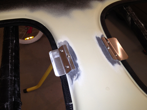
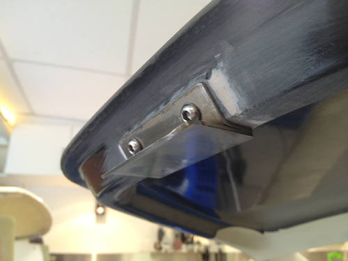
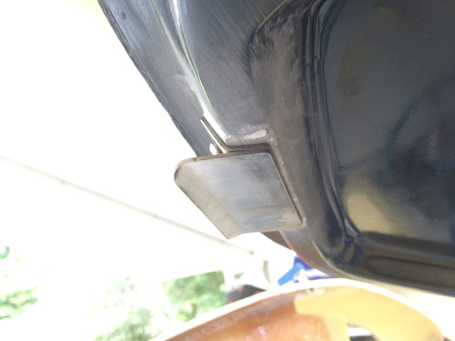
Door Closing Plates
I did not want to fit door eyebrows to keep the doors shut as they look like a pain to line up and could damage the paint. Some have made stainless steel door retainers before so now it was my turn. I wanted them low profile, with no visible welds and with bonded threads into the door and roof structures. The welds on the door retainer plate are through holes on the upper plate to the lower plate.
As can be seen below they are ready for polishing and work great. I recommend this to anyone that would like to not pursue the period correctness of eyebrows on their 40.
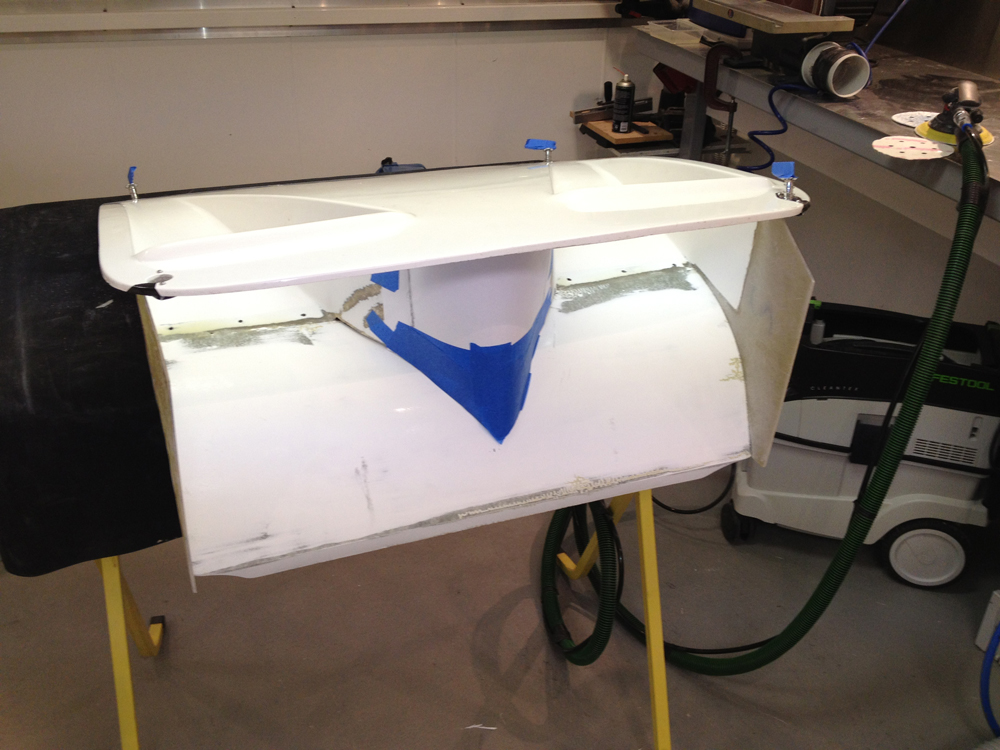
Front "nostril" Panels
I could not decide on what nostril panels to use on by car. After fitting my crazy large radiator I wanted to make sure airflow was optimised. After seeing a depressing amount of good work in this area by many others I decided to do something similar but as always slightly different. I will use the single one on the track and the twin when cooling is not that critical. The twin hides the fans a little more.
First the single. Cut the hell out of it and extend it. Alloy used as a mold surface. Putting a return in the fiberglass at the bottom made the leading edge very rigid.
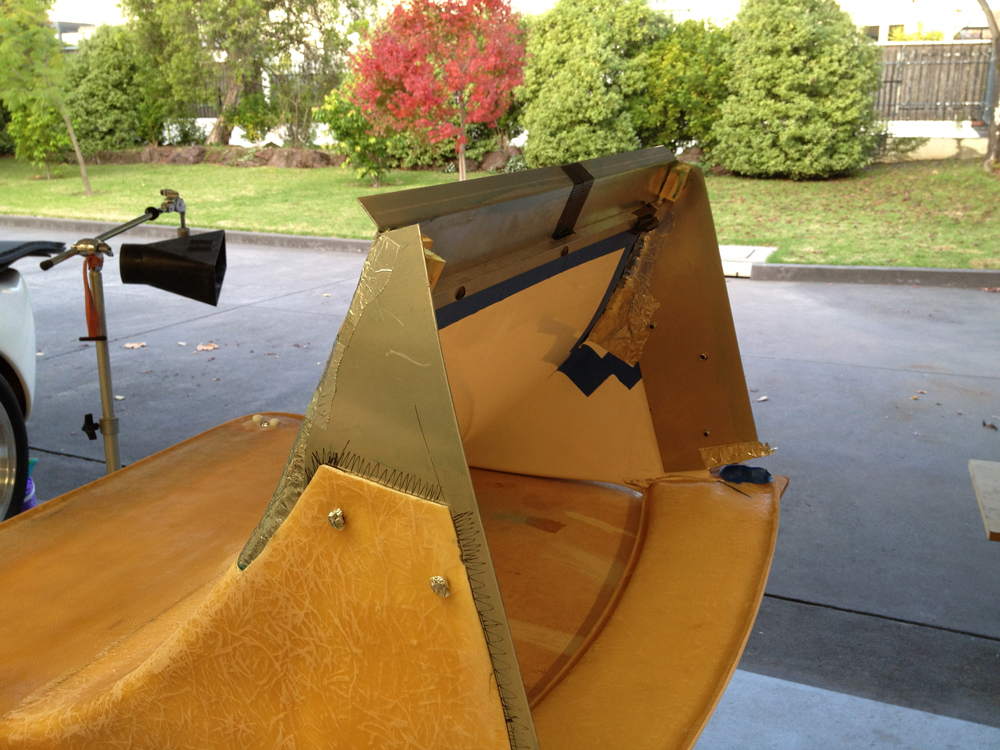
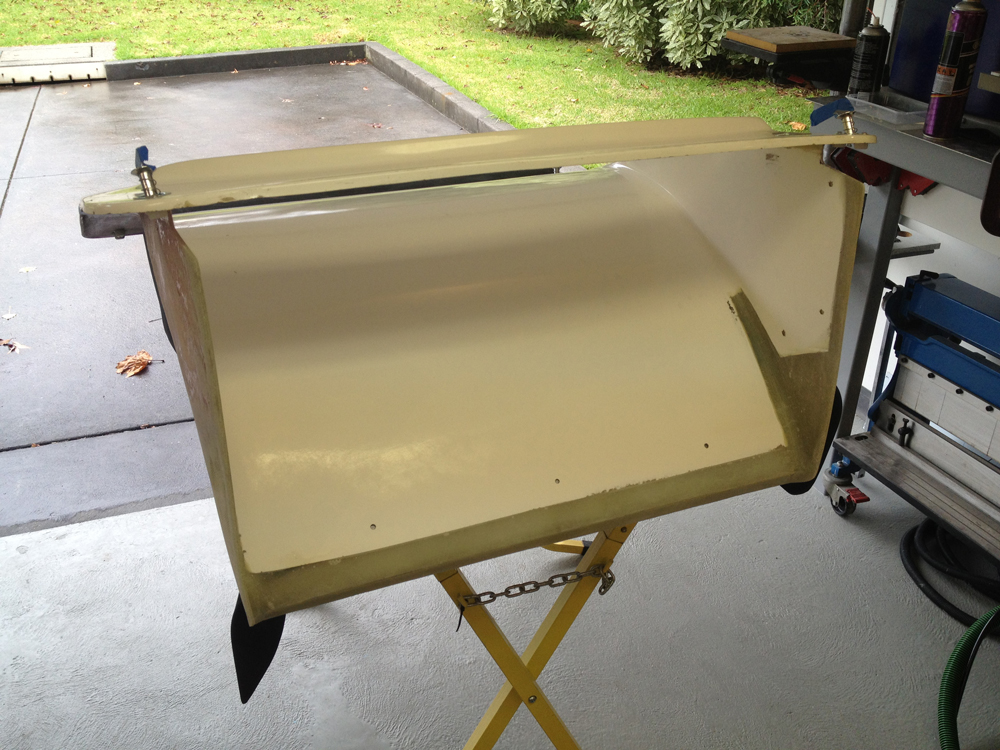
Full flow from the radiator and up and out was achieved.
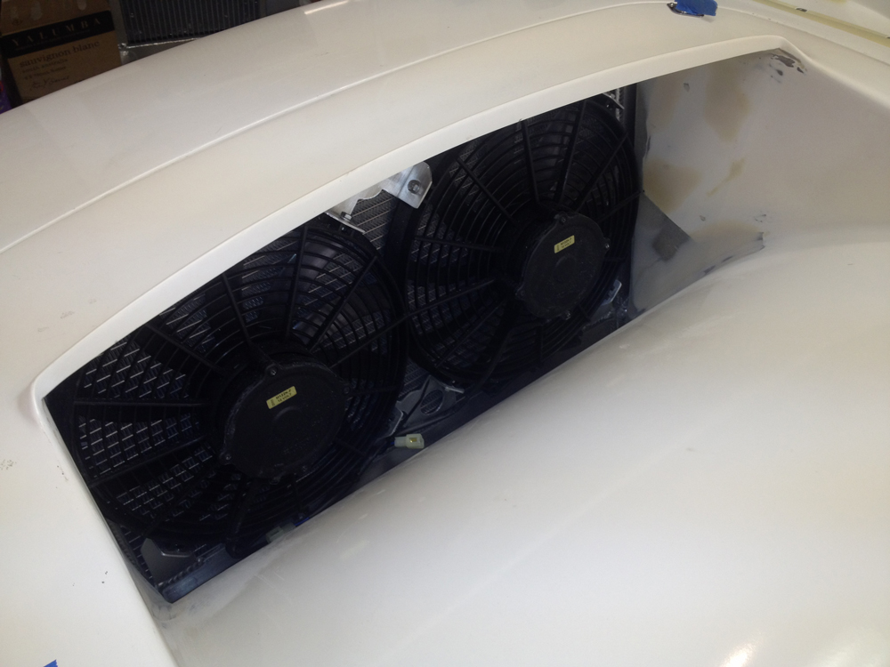
Now the dual.
I then made another alloy form for the extensions.
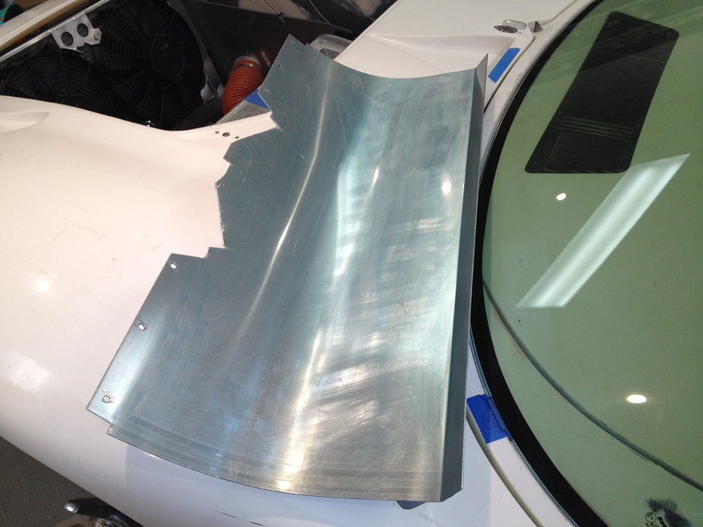
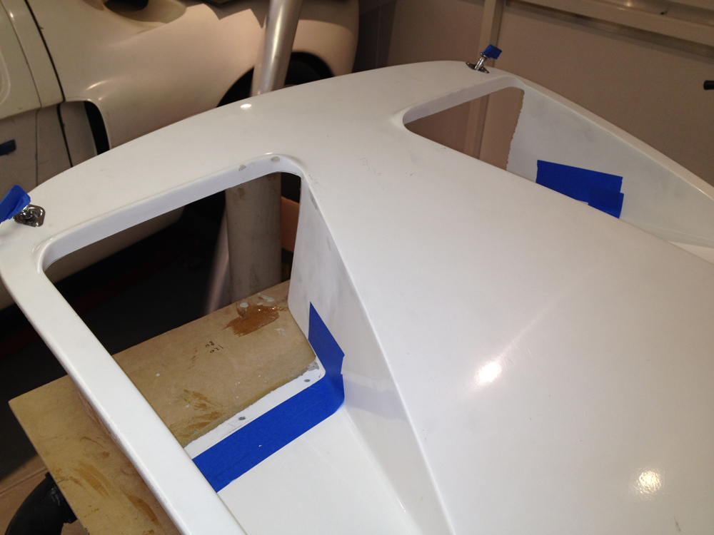
For the nose the above image is a pattern. Another alloy form. Some gel coat below. Then backed up with glass.
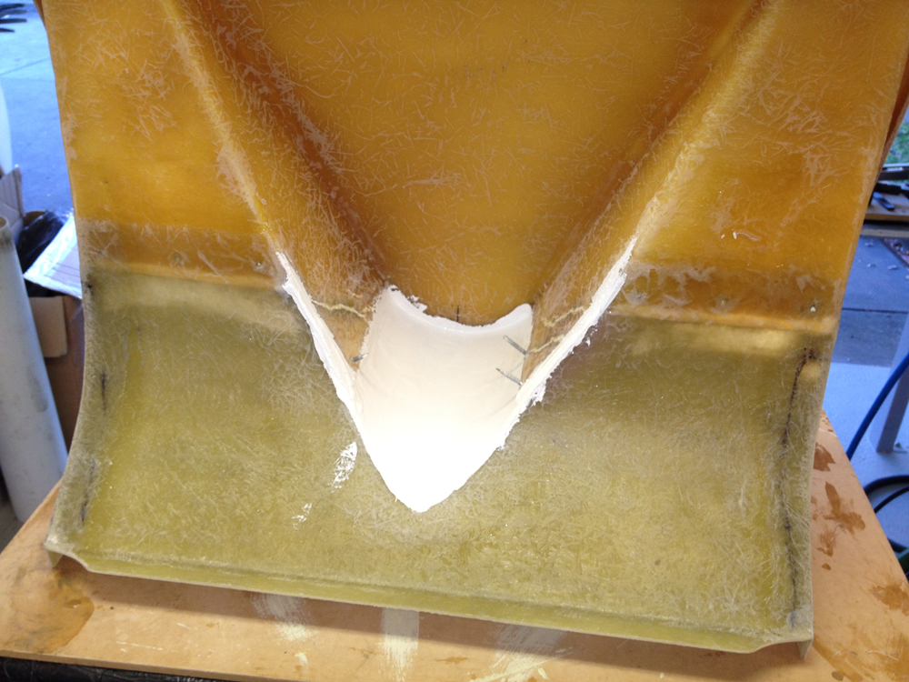
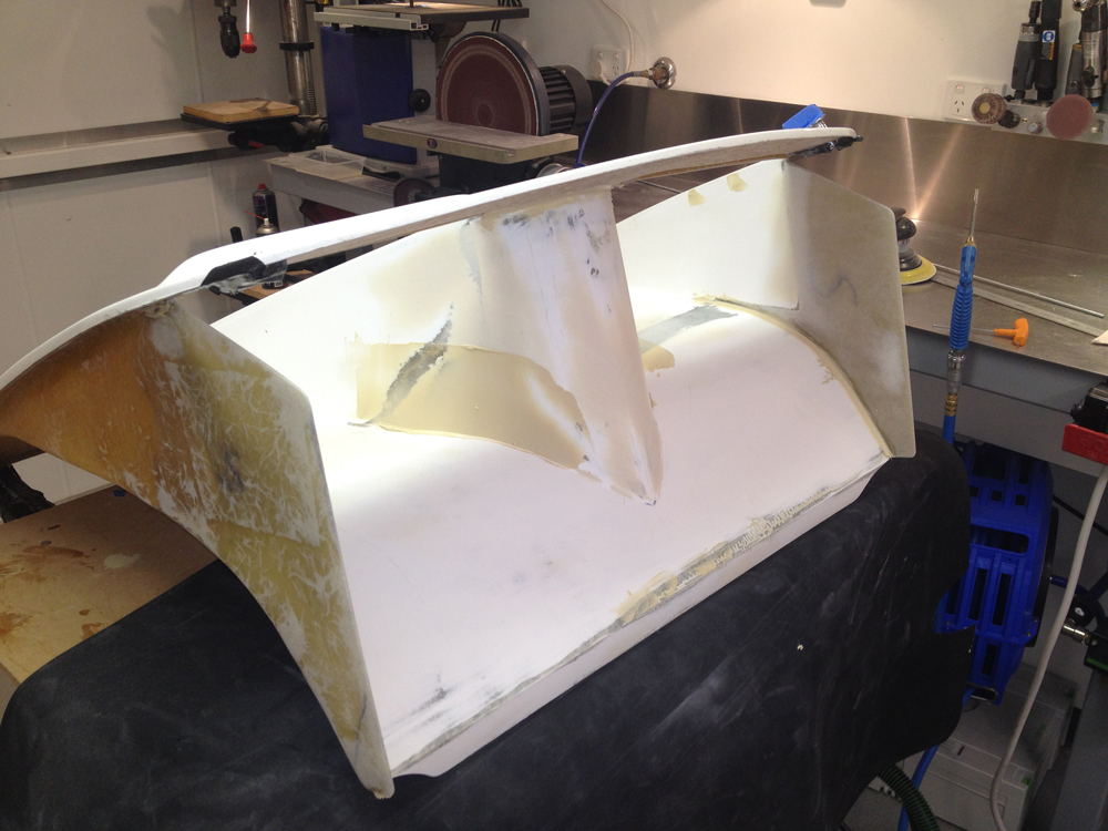
The end result above before finishing gets the air out again. Boy I hate fiberglass!
By the way I'm selling some parts so visit the Garage Sale area of the forum if this post is not ages old!
I could not decide on what nostril panels to use on by car. After fitting my crazy large radiator I wanted to make sure airflow was optimised. After seeing a depressing amount of good work in this area by many others I decided to do something similar but as always slightly different. I will use the single one on the track and the twin when cooling is not that critical. The twin hides the fans a little more.
First the single. Cut the hell out of it and extend it. Alloy used as a mold surface. Putting a return in the fiberglass at the bottom made the leading edge very rigid.
Full flow from the radiator and up and out was achieved.
Now the dual.
I then made another alloy form for the extensions.
For the nose the above image is a pattern. Another alloy form. Some gel coat below. Then backed up with glass.
The end result above before finishing gets the air out again. Boy I hate fiberglass!
By the way I'm selling some parts so visit the Garage Sale area of the forum if this post is not ages old!
Hi Jason Conrad here,nice work again.Are you able to fit some sort of seal around the bottom flange.I have thought about something similar for the car we are building.We have a twin nostril panel .My idea is to fit a shroud around the raditor perimeter that would meet the nostril inlets.Whether this will clear when the front panel opens is another issue.I like the idea of keeping the radiator inlet sealed to the outlets so if driving in the wet you are not collecting road grime and water under the front panel.Keep up the good work.Cheers Conrad
Dimi Terleckyj
Lifetime Supporter
Hi Conrad
Usually when you take the nostril lower section all the way to the bottom of the radiator you can not open the front clip with the nostril hatch in place.
You need to remove the nostril panel first then you can open the front clip.
Dimi
Usually when you take the nostril lower section all the way to the bottom of the radiator you can not open the front clip with the nostril hatch in place.
You need to remove the nostril panel first then you can open the front clip.
Dimi

Dimi is right you need to take them out first before tilting the clip. No big issue. I will not go sealing it I do not expect much leakage. A bit of air under the front clip is not really a concern.
Great work Jas, you obviously spending many late nights in the garage since I was last there.
Have you picked up the Coyote motor, does it fit?????
Peter
Have you picked up the Coyote motor, does it fit?????
Peter
You are right Tom, real GT40s have tilting front clips and its a nice and simple robust setup. But after the 10th time of dropping it as I removed it on my own I thought screw this, when its painted this will suck!
Peter, regarding the Australian Ford Coyote engine (very similar to US one) it will not fit without major surgery, Fran was right.
I have another engine coming in from the USA as we speak. This one will be an interesting challenge!!!!
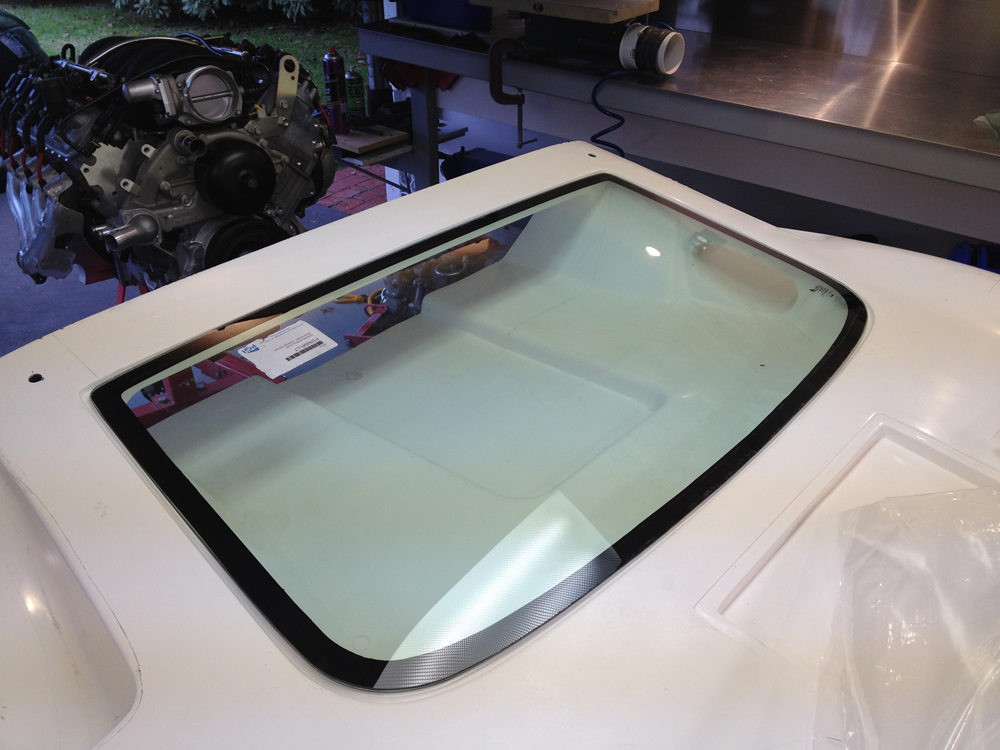
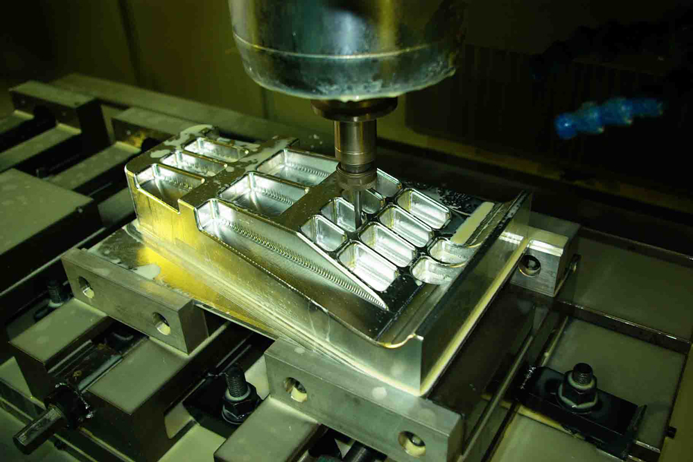
I wanted to swap the rear cabin window differently to other RCRs in glass and with a custom frame. I designed an alloy frame in CAD and had it NC machined out of plate. It came out great but it will be hardly seen so this is another one of those "i did it because I wanted to!" parts")
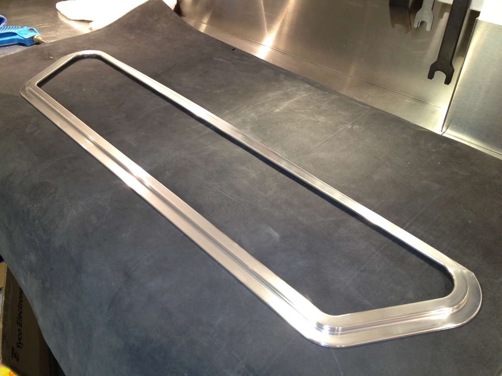
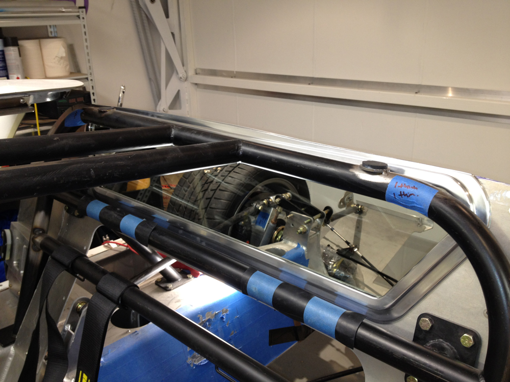
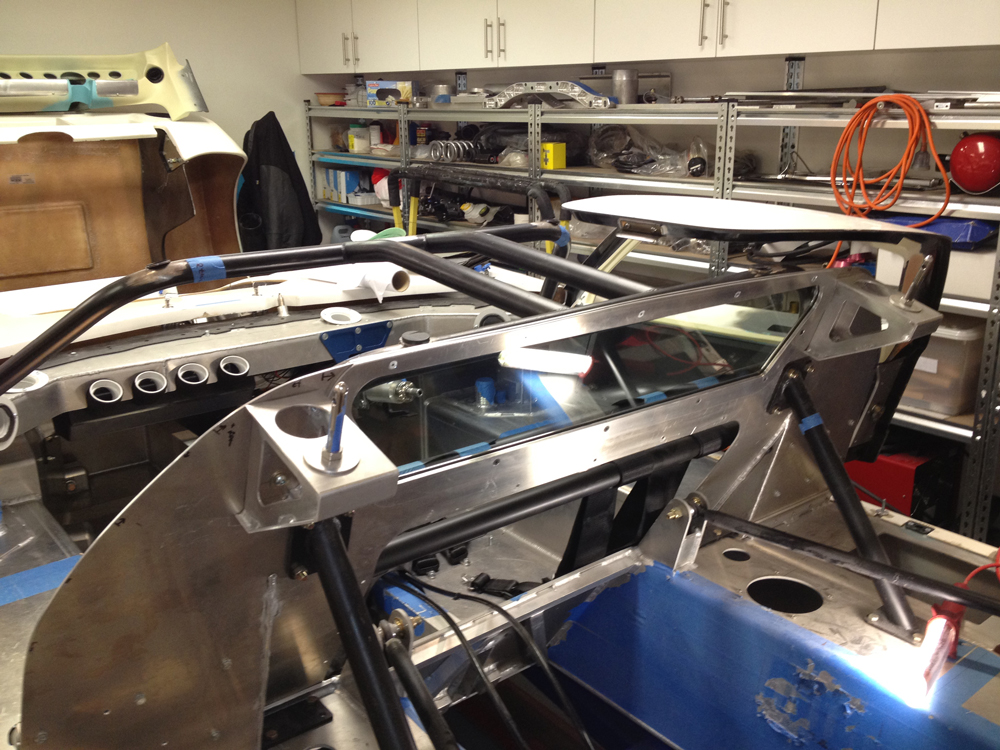
The rear window from Roaring Forties was also trimmed slightly to fit the RCR rear clip. I needed to get more Australian content in the car to be recognised by other GT40 drivers over here!
I also sold my GM engine in the background. Now when is the next one arriving!
Peter, regarding the Australian Ford Coyote engine (very similar to US one) it will not fit without major surgery, Fran was right.
I have another engine coming in from the USA as we speak. This one will be an interesting challenge!!!!
I wanted to swap the rear cabin window differently to other RCRs in glass and with a custom frame. I designed an alloy frame in CAD and had it NC machined out of plate. It came out great but it will be hardly seen so this is another one of those "i did it because I wanted to!" parts
The rear window from Roaring Forties was also trimmed slightly to fit the RCR rear clip. I needed to get more Australian content in the car to be recognised by other GT40 drivers over here!
I also sold my GM engine in the background. Now when is the next one arriving!
Thanks Trevor. Please note the shape is standard RCR, I just changed the cabin side frame. All fastener positions are also standard RCR.
Finally got some work done. I wanted to have a transaxle mount from the rear cross member to the OE mounting point on the transaxle. It is probably not required (other cars just hang the transaxle off the bell housing and are running around OK) but I wanted to do it. I mocked up the part in cardboard, then to CAD and had one NC machined out of 6061T6 Aluminium. The worry when such a part turns up is that one gets a dimension wrong and a hole does not line up or something. Luckily it fit perfect first time.
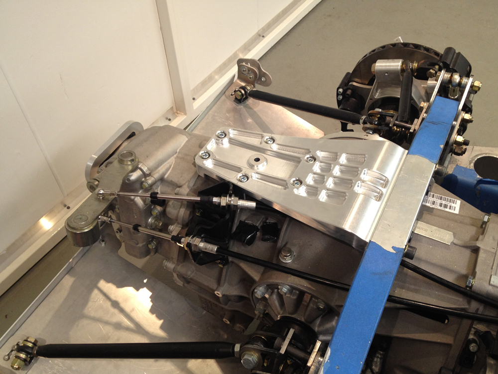
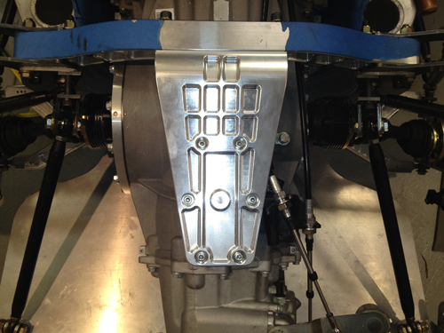
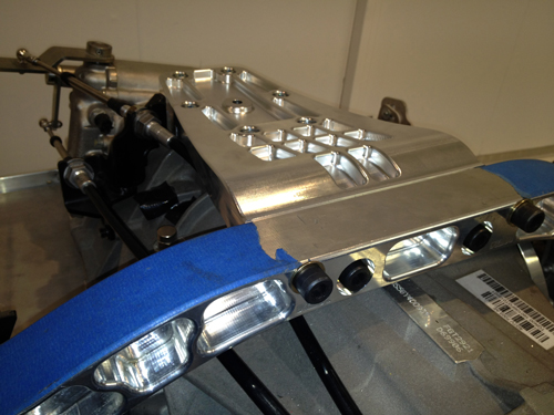
While I was at it I also made a cover for the rear of the transaxle as the raw gearbox casting looks like rubbish and it can be seen at the rear of the car.
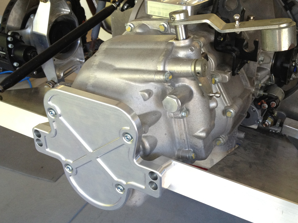
While I was at it I also made a cover for the rear of the transaxle as the raw gearbox casting looks like rubbish and it can be seen at the rear of the car.
Suspension Mount Hardware. I also made some new parts for various parts of the metal work to strengthen up the upper shock & cross member mounts mounts and support the single shear lower suspension bolt as well as a few other mods. Most of the modifications are due to the large transaxle and I intend to give the car a hard time when it runs.
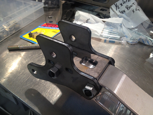
Additional bolt to the chassis allows the aluminium cross member to be removed without the suspension shock tower from collapsing which will make engine removal simpler in the future.
The brace below supports the lower suspension bolts that are in single shear. It also allows the removal of the bottom cover plate without removing the lower suspension arms (standard configuration).
Nice...and beefy.
the lower rear suspension bolt is not usually in single shear though...the second 5/8 hole above the control arm mount is normally used to provide double shear bracing, but obviously with your trans its not a possibility....
the lower rear suspension bolt is not usually in single shear though...the second 5/8 hole above the control arm mount is normally used to provide double shear bracing, but obviously with your trans its not a possibility....
Frans comment is spot on regarding the potential to add a double shear brace if it was not for the position of my transaxle. Also the mods to the upper shock mounts are largely due to the fact that the alloy cross member was raised about 10mm to clear the top of the transaxle. When you change a small thing the effects can roll on to other areas!
Very nice Jason, very nice.
Jim
Jim
Thanks for the comments Jim, but this is just engineering, your car body is taking real skill to fabricate from scratch.
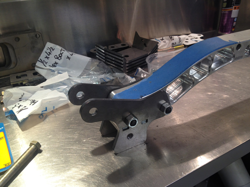
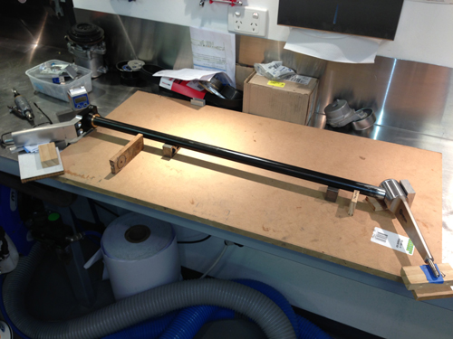
Sway Bars (Anti-roll Bars)
I really wanted to fit adjustable blade type sway bars to the GT40. Problem as always was space. I purchased the blades, bars and fixed arms from Genesis Technologies Race Car Parts and Equipment. Pillow blocks for the bars were sourced elsewhere and are alloy with self centering bushes fitted in them, very nice units.
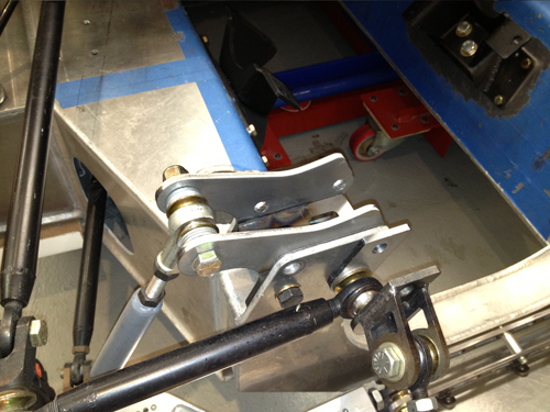
REAR
When I made the transaxle mount I left clearance between the mount and the transaxle for a bar. The modifications to the shock uprights also accommodate the sway bar bearing mounts.
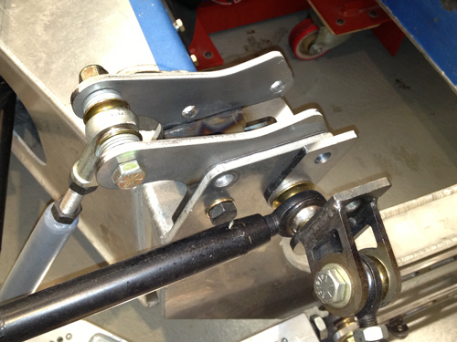
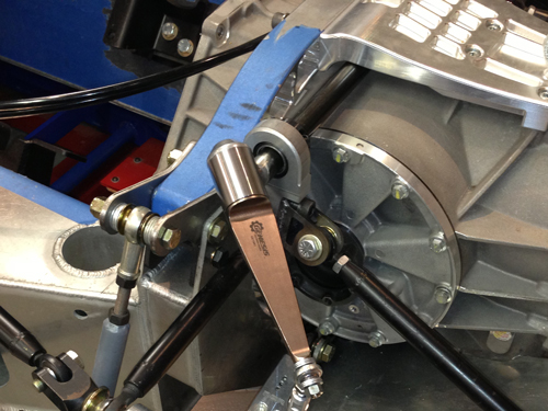
The sway bars are hollow 25mm diameter. At the end of the "blade" arm above are bearings in the supporting tube that allow it to rotate and adjust the sway bar. These are pretty common units in race applications. I used a spline on the end where the bar connects to the rigid arm so the removal of the assembly is easy. The rigid arm was milled and bolted to bend it rather than heating it up etc. The end result is very strong and exact.
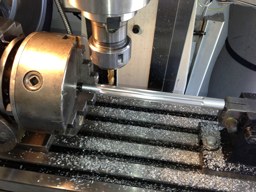
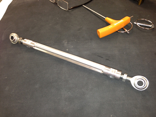
Drop links were turned up on the lathe and groved in the mill.
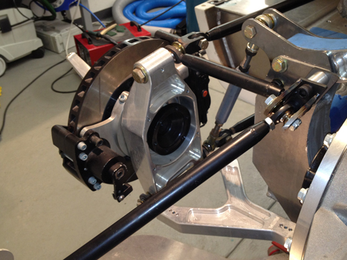
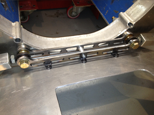
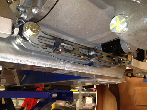
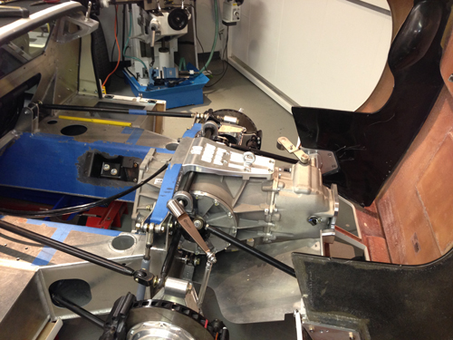
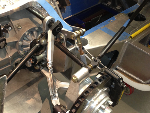
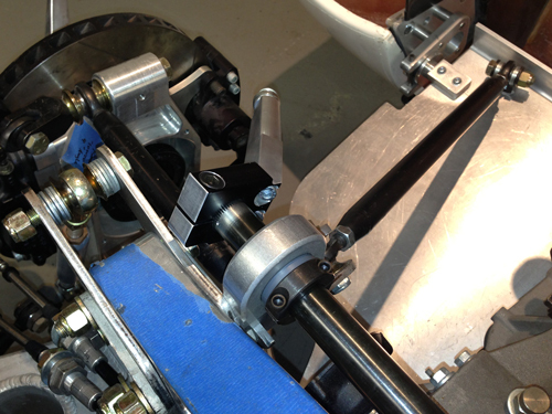
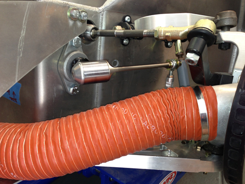
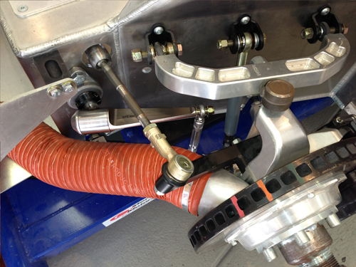
FRONT
The front bar was routed through the chassis to keep the space ahead of the footbox clear. The self centering bearings ensured the bar does not bind due to it being impossible to get both sides of the chassis parallel. Missing the brake cooling duct in all suspension & steering lock combinations was tough.
Sway Bars (Anti-roll Bars)
I really wanted to fit adjustable blade type sway bars to the GT40. Problem as always was space. I purchased the blades, bars and fixed arms from Genesis Technologies Race Car Parts and Equipment. Pillow blocks for the bars were sourced elsewhere and are alloy with self centering bushes fitted in them, very nice units.
REAR
When I made the transaxle mount I left clearance between the mount and the transaxle for a bar. The modifications to the shock uprights also accommodate the sway bar bearing mounts.
The sway bars are hollow 25mm diameter. At the end of the "blade" arm above are bearings in the supporting tube that allow it to rotate and adjust the sway bar. These are pretty common units in race applications. I used a spline on the end where the bar connects to the rigid arm so the removal of the assembly is easy. The rigid arm was milled and bolted to bend it rather than heating it up etc. The end result is very strong and exact.
Drop links were turned up on the lathe and groved in the mill.
FRONT
The front bar was routed through the chassis to keep the space ahead of the footbox clear. The self centering bearings ensured the bar does not bind due to it being impossible to get both sides of the chassis parallel. Missing the brake cooling duct in all suspension & steering lock combinations was tough.
Similar threads
- Replies
- 21
- Views
- 2K