M6B Tragic

Howard Jones

Supporter
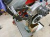
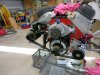
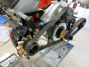
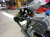
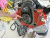
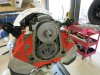
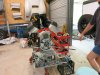
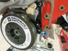
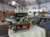
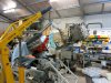
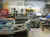
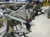
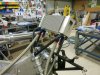
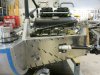
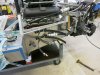
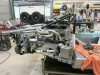
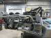
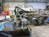
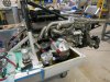
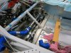
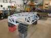
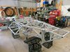
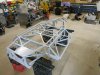
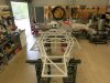
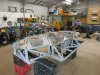
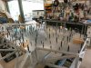
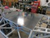
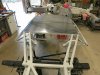
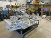
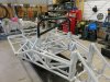
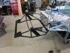
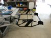
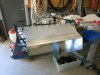
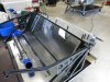
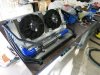
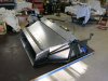
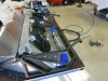
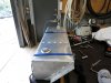
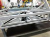
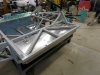
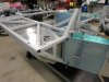
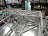
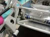
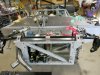
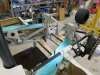
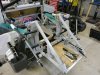
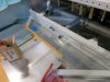
Those of you that are thinking about your own space frame chassis design should have a long and careful look at this chassis. I don't see a single element I would alter. Really thoughtful work.

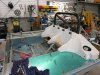
Some of the most interesting scratch builds seam to come from the southern hemisphere. Really nice build and careful design. I will watch with great interest and I will continue to learn things in the process.

Thanks for posting all those pictures.
 
This is when I got my chassis back and then made the floor plate out of 3mm marine grade alloy. I used Sikaflex as well as the rivets. Flipped it over and started drilling holes. Lots and lots of holes.
 

Attachments

  • IMG_1505.JPG
    IMG_1505.JPG
    408.4 KB · Views: 716
  • IMG_1506.JPG
    IMG_1506.JPG
    427.7 KB · Views: 638
  • IMG_1507.JPG
    IMG_1507.JPG
    398.6 KB · Views: 509
  • IMG_1508.JPG
    IMG_1508.JPG
    414.1 KB · Views: 487
  • IMG_1512.JPG
    IMG_1512.JPG
    438.4 KB · Views: 491
  • IMG_1513.JPG
    IMG_1513.JPG
    413.9 KB · Views: 485
  • IMG_1514.JPG
    IMG_1514.JPG
    366.6 KB · Views: 488
  • IMG_1516.JPG
    IMG_1516.JPG
    344.5 KB · Views: 484
  • IMG_1518.JPG
    IMG_1518.JPG
    420.5 KB · Views: 502
  • IMG_1519.JPG
    IMG_1519.JPG
    410.1 KB · Views: 530
Thankyou Michel, fine praise coming from you, after seeing what you've built

Neil, I'm sorry but I didn't keep count.

Here are some pictures of the front radiator sub frame. I'm trial fitting it after the sand blasting. It's amazing how things distort. Then I completed it with the alloy panelling to duct all air through the radiator.
 

Attachments

  • IMG_1548.JPG
    IMG_1548.JPG
    348.5 KB · Views: 486
  • IMG_1550.JPG
    IMG_1550.JPG
    310 KB · Views: 460
  • IMG_1596.JPG
    IMG_1596.JPG
    282.6 KB · Views: 485
  • IMG_1598.JPG
    IMG_1598.JPG
    282.6 KB · Views: 456
  • IMG_1599.JPG
    IMG_1599.JPG
    337.4 KB · Views: 452
  • IMG_1568.JPG
    IMG_1568.JPG
    337.7 KB · Views: 479
  • IMG_1604.JPG
    IMG_1604.JPG
    426.9 KB · Views: 451
  • IMG_1605.JPG
    IMG_1605.JPG
    345.9 KB · Views: 456
  • IMG_1606.JPG
    IMG_1606.JPG
    349.9 KB · Views: 487

Neil

Supporter
Udo, if you are seeing distortion after sandblasting, the blaster is using too high air pressure. The abrasive needs to clean the surface, not remove material or work harden the material. Often sand blasters don't discard their worn-out abrasive and simply turn up the air pressure to make it work for a little while longer.
 
This is when I made my fuel tanks, the driver side is narrower due to the gear change and the water flow and return pipes going down that side. I installed a fuel sender unit to take some of the guess work out of knowing how many more laps can I get in. They are balanced together before going to filters and pumps.
Hi Neil, you're probably dead right, I'm not really seeing that much, just a bit, but that could also be me doing the final welding.
 

Attachments

  • IMG_1541.JPG
    IMG_1541.JPG
    340.5 KB · Views: 427
  • IMG_1540.JPG
    IMG_1540.JPG
    285.5 KB · Views: 423
  • IMG_1542.JPG
    IMG_1542.JPG
    296.1 KB · Views: 415
  • IMG_1545.JPG
    IMG_1545.JPG
    307.5 KB · Views: 426
  • IMG_1577.JPG
    IMG_1577.JPG
    333 KB · Views: 415
  • IMG_1578.JPG
    IMG_1578.JPG
    333.6 KB · Views: 409
  • IMG_1579.JPG
    IMG_1579.JPG
    302.2 KB · Views: 411
  • IMG_1581.JPG
    IMG_1581.JPG
    289.3 KB · Views: 414
  • IMG_1590.JPG
    IMG_1590.JPG
    291.8 KB · Views: 398
  • IMG_1592.JPG
    IMG_1592.JPG
    356.2 KB · Views: 421
I fixed a plate of 3mm alloy to the top of the frame behind the back of the seat to sit all the fuel lines, filters and pump etc. Also to fix the swirl pot and water pipes to. Then it was back to a bit of glass work getting the seat in shape and recessing the fuel filler openings. Also fitting the rear side sill ends where HP fuel pump, more filters and surge tanks goes. Oil tank and catch can on other side. Received my spacers and pins and stuff back from platers. We don't have anyone in Darwin, so they have to be sent to Adelaide. Talk about Backwater, Hey?
 

Attachments

  • IMG_1583.JPG
    IMG_1583.JPG
    288.2 KB · Views: 405
  • IMG_1584.JPG
    IMG_1584.JPG
    347.3 KB · Views: 410
  • IMG_1593.JPG
    IMG_1593.JPG
    313.1 KB · Views: 429
  • IMG_1649.JPG
    IMG_1649.JPG
    389.8 KB · Views: 416
  • IMG_1658.JPG
    IMG_1658.JPG
    395.8 KB · Views: 414
  • IMG_1661.JPG
    IMG_1661.JPG
    426.6 KB · Views: 400
  • IMG_1678.JPG
    IMG_1678.JPG
    279.8 KB · Views: 403
  • IMG_1571.JPG
    IMG_1571.JPG
    382.2 KB · Views: 434
After getting sick of waiting about three and a half years for my Calipers from you know who. I decided to order some from AP who make a replacement of the Original Lockhead units. CP2270 on the front and CP2271 on the rear. The only issue is, they come with blank ears which you have to machine to suit your individual application. Enter my mate Clayton who has a Lathe and Milling machine. As expected they fitted perfectly. Friends like him are invaluable, can't praise him enough.
 

Attachments

  • IMG_1556.JPG
    IMG_1556.JPG
    351.2 KB · Views: 381
  • IMG_1557.JPG
    IMG_1557.JPG
    282.4 KB · Views: 384
  • IMG_1559.JPG
    IMG_1559.JPG
    286.4 KB · Views: 390
  • IMG_1570.JPG
    IMG_1570.JPG
    306.9 KB · Views: 435
  • IMG_1609.JPG
    IMG_1609.JPG
    346.4 KB · Views: 376
  • IMG_1610.JPG
    IMG_1610.JPG
    261.1 KB · Views: 404
  • IMG_1611.JPG
    IMG_1611.JPG
    338.2 KB · Views: 409
  • IMG_1612.JPG
    IMG_1612.JPG
    324.9 KB · Views: 397
  • IMG_1615.JPG
    IMG_1615.JPG
    398.6 KB · Views: 431
Back again with some more progress pictures. This time it's brake and clutch lines, plus setting up the master cylinders and the reservoirs'. Then covering them up.
 

Attachments

  • IMG_1655.JPG
    IMG_1655.JPG
    328.4 KB · Views: 381
  • IMG_1662.JPG
    IMG_1662.JPG
    370.9 KB · Views: 424
  • IMG_1674.JPG
    IMG_1674.JPG
    396.6 KB · Views: 389
  • IMG_1675.JPG
    IMG_1675.JPG
    388.9 KB · Views: 384
  • IMG_1822.JPG
    IMG_1822.JPG
    271.8 KB · Views: 377
  • IMG_1816.JPG
    IMG_1816.JPG
    322.4 KB · Views: 365
  • IMG_1891.JPG
    IMG_1891.JPG
    294.2 KB · Views: 377
  • IMG_1892.JPG
    IMG_1892.JPG
    276.1 KB · Views: 421
  • IMG_1897.JPG
    IMG_1897.JPG
    304.9 KB · Views: 450
As usual an excellent progress !!!
You are really building an fantastic jewell.............;)
Again lots of congratulations
It's a shame we are so far ..... will be very interested to fight on track VS you and your "coming beast" with my "little 907":D:D:D
 
Thanks for the encouraging kind words Michel and Mesa, my wife is the one that gave me the M6B Tragic title Mesa, She thinks that's what I am. I've loved these things ever since I saw Denny Hulme drive Bob Jane's car around the Adelaide F1 track on the first time of the event back in the 80's.
Here are some more progress Pics. Making up alternator brackets, fitting Dry sump. Tapping the block to fit the Kinsler valley plate, I bought a Big Block Crank Trigger Ignition Conversion Kit, which comes with a double row timing chain, so had to grind away the block for it to fit. Then put front end back together.
Andy, I had a local company called L&S Springs have them outsourced by another company called Fulcrum Suspension in Qld. Only problem is they have about 9 outlets. I spoke to a guy called Marty. I'll see if I can find out which outlet he is at.
 

Attachments

  • IMG_1503.JPG
    IMG_1503.JPG
    333.9 KB · Views: 407
  • IMG_1663.JPG
    IMG_1663.JPG
    370 KB · Views: 391
  • IMG_1664.JPG
    IMG_1664.JPG
    380.9 KB · Views: 366
  • IMG_1666.JPG
    IMG_1666.JPG
    289.5 KB · Views: 366
  • IMG_1668.JPG
    IMG_1668.JPG
    400.5 KB · Views: 369
  • IMG_1670.JPG
    IMG_1670.JPG
    388.3 KB · Views: 374
  • IMG_1683.JPG
    IMG_1683.JPG
    292.2 KB · Views: 359
  • IMG_1684.JPG
    IMG_1684.JPG
    357.6 KB · Views: 371
  • IMG_1685.JPG
    IMG_1685.JPG
    369.1 KB · Views: 374
  • IMG_1686.JPG
    IMG_1686.JPG
    367.5 KB · Views: 381
Thanks Rex, Looking forward to seeing your Mk IV make a start.
More pictures, I'm trying to get a backlog out the way.
Engine back together, Sensor won't fit, make little brackets up to reposition sensor and fit timing pointer, Flywheel and starter motor fitted, Clutch fitted, Transaxle back on. Then I had to take a couple of pictures of the engine before it went back in because I love the look of a BBC with the fuel injection like they had back in the Can-Am days. Then, in it goes, and it's back in, Yay!
You'll notice a set of hairy knuckles pointing to things now and then, that's my mate Clayton who I've mentioned before. He's always helping out with advice, engine stuff and machining things. Can't thank him enough. Thanks Clayton.
 

Attachments

  • IMG_1690.JPG
    IMG_1690.JPG
    377.7 KB · Views: 353
  • IMG_1687.JPG
    IMG_1687.JPG
    377.1 KB · Views: 394
  • IMG_1692.JPG
    IMG_1692.JPG
    317.1 KB · Views: 358
  • IMG_1697.JPG
    IMG_1697.JPG
    355.7 KB · Views: 353
  • IMG_1701.JPG
    IMG_1701.JPG
    351.8 KB · Views: 359
  • IMG_1710.JPG
    IMG_1710.JPG
    320.8 KB · Views: 358
  • IMG_1752.JPG
    IMG_1752.JPG
    384.9 KB · Views: 364
  • IMG_1749.JPG
    IMG_1749.JPG
    417.2 KB · Views: 366
  • IMG_1759.JPG
    IMG_1759.JPG
    466.5 KB · Views: 413
  • IMG_1760.JPG
    IMG_1760.JPG
    426.8 KB · Views: 380
Andy with his magnificent M20 build has encouraged me to start posting more progress pictures, so here goes.
These are of me slowly putting things back together, also starting the fuel system.
 

Attachments

  • IMG_1784.JPG
    IMG_1784.JPG
    379.4 KB · Views: 231
  • IMG_1785.JPG
    IMG_1785.JPG
    432.6 KB · Views: 216
  • IMG_1788.JPG
    IMG_1788.JPG
    333.3 KB · Views: 219
  • IMG_1789.JPG
    IMG_1789.JPG
    391.8 KB · Views: 220
  • IMG_1798.JPG
    IMG_1798.JPG
    433.5 KB · Views: 226
  • IMG_1805.JPG
    IMG_1805.JPG
    418.2 KB · Views: 214
  • IMG_1823.JPG
    IMG_1823.JPG
    410.5 KB · Views: 218
  • IMG_1826.JPG
    IMG_1826.JPG
    381.8 KB · Views: 221
  • IMG_1821.JPG
    IMG_1821.JPG
    367.5 KB · Views: 223
  • IMG_1816.JPG
    IMG_1816.JPG
    322.4 KB · Views: 228
Hi again, I am using a Kinsler Bear Claw fuel injection and it doesn't have any provision for a thermostat housing, so I have had to make something myself, again enlisting the help of my good friend Clayton and his Lathe. Here is what I came up with.
 

Attachments

  • IMG_1407.JPG
    IMG_1407.JPG
    300.8 KB · Views: 259
  • IMG_1829.JPG
    IMG_1829.JPG
    408.9 KB · Views: 221
  • IMG_1830.JPG
    IMG_1830.JPG
    262.4 KB · Views: 249
  • IMG_1831.JPG
    IMG_1831.JPG
    267 KB · Views: 250
  • IMG_6554.JPG
    IMG_6554.JPG
    329.4 KB · Views: 220
  • IMG_6556.JPG
    IMG_6556.JPG
    328.1 KB · Views: 201
  • IMG_6557.JPG
    IMG_6557.JPG
    206.9 KB · Views: 210
  • IMG_6560.JPG
    IMG_6560.JPG
    344.2 KB · Views: 210
  • IMG_6564.JPG
    IMG_6564.JPG
    307.8 KB · Views: 209
  • IMG_6566.JPG
    IMG_6566.JPG
    312.9 KB · Views: 208
Back
Top