
You are using an out of date browser. It may not display this or other websites correctly.
You should upgrade or use an alternative browser.
You should upgrade or use an alternative browser.
Mclaren M8b replica (visual)
- Thread starter russell keach
- Start date
Terry Oxandale
Skinny Man
I'm sorry to hear the bad news. My thoughts are for your daughter's family's well-being during this time. Such a young age for this kind of thing to happen. I would hope my end would be as peaceful as that appeared to be.
Hi Russell. I am very sorry to hear of your family's loss.
Manifolds look great, I am very interested in this as I plan to (eventually) do exactly the same. If you are prepared to let me have the DXF files / drawing of the flanges and your build notes this would be much appreciated. My E mail is [email protected]
Cheers
Fred W B
Manifolds look great, I am very interested in this as I plan to (eventually) do exactly the same. If you are prepared to let me have the DXF files / drawing of the flanges and your build notes this would be much appreciated. My E mail is [email protected]
Cheers
Fred W B
Fred
Sorry for the delay...been a bit occupied, then went on holiday.
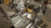
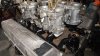
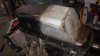
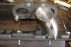
Finished the other head outlet port to the cooling system so now all the bits will get a coating of (POR 15) which should keep the corrosion at bay. With all the ancillary parts made for the motor, its time to pull that down and freshen it up. I had planned to just run it stock....good thing that plans are just that as I have now got a medium cam, new followers, heads ported and the inlet manifolds done to accept the 4 x 40mm Del Orto carbs. I hope to get similar performance to my original car which was 197HP at the rear wheels and that`s plenty when you are only pushing 700kg +-.
With the painting done its now time to find all the bits and start putting it together. Tyres are just waiting to be turned so there is not much more to fabricate apart from body mounts and the radiator surround. Axels will be left till last thing as they will be specials, Subaru at the wheel and Audi at the box.
Looking forward to starting the body work and I have got a good scale drawings with a 100mm grid overlaid so that will help when setting up the mold which will be constructed just like you would form up a boat mold. Still have yet to decide whether to make a male or a female mold...if its only to produce one body then it seems like a good option to put all the finishing work into the final body. All that has to wait until the chassis is a runner and can then be stored off site.
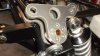
I have included a picture showing the jig I made up to fabricate the inlet mainfold`s in, just a comment in that the bracing or connection between top and bottom needs to be much stronger as I got the same (but opposite) distortion on both sides. Agonized how to solve it with out massive surface grinding and came up with the idea of water jet cutting thick nylon `gaskets` that i can bolt onto the top of the inlets and using the flat across the rocker covers, router the surfaces back to a common level. I had always planned an insulator between the carb`s and motor so this will do it all in one and a few more mm in height will do no harm. I did get a small amount of surface distortion on the manifold to head face so went out and bought a nice big new flat fine file and went for it...job done.
I shall post some more pics as it comes.
Cheers
Leon
Can you please email me [email protected]
Sorry for the delay...been a bit occupied, then went on holiday.
Finished the other head outlet port to the cooling system so now all the bits will get a coating of (POR 15) which should keep the corrosion at bay. With all the ancillary parts made for the motor, its time to pull that down and freshen it up. I had planned to just run it stock....good thing that plans are just that as I have now got a medium cam, new followers, heads ported and the inlet manifolds done to accept the 4 x 40mm Del Orto carbs. I hope to get similar performance to my original car which was 197HP at the rear wheels and that`s plenty when you are only pushing 700kg +-.
With the painting done its now time to find all the bits and start putting it together. Tyres are just waiting to be turned so there is not much more to fabricate apart from body mounts and the radiator surround. Axels will be left till last thing as they will be specials, Subaru at the wheel and Audi at the box.
Looking forward to starting the body work and I have got a good scale drawings with a 100mm grid overlaid so that will help when setting up the mold which will be constructed just like you would form up a boat mold. Still have yet to decide whether to make a male or a female mold...if its only to produce one body then it seems like a good option to put all the finishing work into the final body. All that has to wait until the chassis is a runner and can then be stored off site.
I have included a picture showing the jig I made up to fabricate the inlet mainfold`s in, just a comment in that the bracing or connection between top and bottom needs to be much stronger as I got the same (but opposite) distortion on both sides. Agonized how to solve it with out massive surface grinding and came up with the idea of water jet cutting thick nylon `gaskets` that i can bolt onto the top of the inlets and using the flat across the rocker covers, router the surfaces back to a common level. I had always planned an insulator between the carb`s and motor so this will do it all in one and a few more mm in height will do no harm. I did get a small amount of surface distortion on the manifold to head face so went out and bought a nice big new flat fine file and went for it...job done.
I shall post some more pics as it comes.
Cheers
Leon
Can you please email me [email protected]
Attachments

Terry Oxandale
Skinny Man
Great job Russ.
I painted a roll cage with POR15 one time. The only issue I had with that was the portions that had not rusted (vs a slight surface rust from sweaty hands I guess) did not hold the paint as well as the rusted portions. I found the paint chipped off the shiny steel tubing much easier than the surface rusted portions (in fact the rusted portions never chipped off at all). I thoroughly cleaned the surfaces of the metal, but the rust seemed to give the paint something to grip onto.
I painted a roll cage with POR15 one time. The only issue I had with that was the portions that had not rusted (vs a slight surface rust from sweaty hands I guess) did not hold the paint as well as the rusted portions. I found the paint chipped off the shiny steel tubing much easier than the surface rusted portions (in fact the rusted portions never chipped off at all). I thoroughly cleaned the surfaces of the metal, but the rust seemed to give the paint something to grip onto.
Just does not seem to 'cover' evenly. I had some chassis bits to paint recently and decided the grey would be ideal, another customer warned me of the problem he had experienced with it, I tried it and have to agree, just glad its in an area where it wont be under much public view, would have removed it, but its such a bitch to get off when dry... as for its corrosion control factors time will tell.
You need to use an etching acid to prep bare steel.. A product calle Metal-Ready works quite nicely.. Once painted with POR15, it's about as tough as a good powder coating..
Silver POR has a problem with turning a slight green hue if exposed to UV for long..
...
If you spray it, you REALLY need to wear breathing apparatus along with a hood and have every square inch of your body covered. What you get on your skin will not wash off with anything. It needs to wear off...
Silver POR has a problem with turning a slight green hue if exposed to UV for long..
...
If you spray it, you REALLY need to wear breathing apparatus along with a hood and have every square inch of your body covered. What you get on your skin will not wash off with anything. It needs to wear off...
Have to agree with Jac, that`s the stuff i used first time and was far from happy. I used a paint stripper called `Dads paint stripper` and it took the fresh cured paint off like magic. Still it was all a waste of time.
Jac, I am stripping down my Subaru Impreza axels (front) and want to take the axel out of the wheel end CV, have been told that the centre star is retained by a small circlip that will just `shock off` once it is hit with a copper hammer.
Well my 2lb steel club hammer very firmly applied to a solid brass drift with the axel firmly held in a vice has no effect, any suggestions thanks.
Cheers
Have to agree with Jac, that`s the stuff i used first time and was far from happy. I used a paint stripper called `Dads paint stripper` and it took the fresh cured paint off like magic. Still it was all a waste of time.
Jac, I am stripping down my Subaru Impreza axels (front) and want to take the axel out of the wheel end CV, have been told that the centre star is retained by a small circlip that will just `shock off` once it is hit with a copper hammer.
Well my 2lb steel club hammer very firmly applied to a solid brass drift with the axel firmly held in a vice has no effect, any suggestions thanks.
Cheers
Russell. Yes the axles should 'shock' out of the CV 'star', but the circlip wont come out of the groove, it gets compressed into the groove by a taper that is machined in the star just outside the spline dia, eg the 'star' slides over the circlip. I find it works better if you hang or hold the axle vertical in a vice or fixture while using punch/hammer to apply the shock force to the star ( a 'C' shaped piece of tube with ID slightly larger than spline welded to a piece of solid scrap bar about 2 ft long so that you get a solid blow to the bar adjacent to the axle is sometimes more effective)... [ I have also watched guys temporarily refit the hub flange and stand on that with both feet while pushing the axle/cv unit fully home, then giving the axle a quick hard yank upwards ( no comments from the cheap seats please!).]
Hi Russell, The car is coming along well. I guess you will be starting your body soon, its great fun to see it come together and I know for myself, I feel like it is actually a car now. I had the same issue with Nissan axles and found if you hold the axle even in your hand and get someone to whack the cv it will come out. The Nissan does seem to be a bit hard on the circlip and the end peice of the spline however. I sent you an email last week when you posted and asked me to, did you recieve it??
Cheers Leon.
Cheers Leon.
Hi
Been without my computer for some weeks now so back on deck with progress to report.
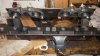
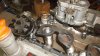
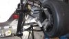
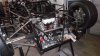
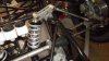
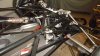
Those Subaru axel`s were immovable and once i found brand new cv`s for $50.00 each i soon scrapped the old ones. I have completed the inlet manifolds and they are stacked away. All the front and rear suspension has been fitted and set up approximately. The front inboard rocker arms have been laser cut from 10mm alloy and had a bronze bush fitted in the central pivot, all that remains now for the front end is to sit it on its wheels with the load on so that ride height can be set up...its been all guess work on loads so far. The steering shaft and rack position has been set up at best to account for any bump steer and the brake master cylinders and remote reservoirs have also been installed. As expected, there has also been a lot of fabrication involved with these parts. The steering rack started out as a Ford Escort and now the shaft has been widened and modern Mazda tie rod ends fitted. These fit straight onto the MX5 rod ends so apart from the shaft, all components are standard.
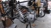
Now that the chassis has progressed to this point, i have started to work on the motor which had been in storage for over 15 years. On strip down, there was even straw on the valves. Good thing is that the cam and followers are in perfect condition so will sell them to help pay for the new performance cam and followers. As the heads were in perfect condition with the valve guides like new, a quick valve grind brought the valves up perfect. I have decided to send my short block to the professionals and have it honed and re ringed as the bore was almost perfect with no wear visable and a new timing chain will complete the rebuild. I will probably fit an electronic Chev distributor if my Rover one proves not up to it. The sump capacity has also been extended with trap doors to prevent oil surge under brakes. I have been watching Leon`s body work build with envy and can not wait to tart mine.....but do want to have it to a running mobile stage before i turn my work shop into a dust bowl!
Next week i hope to have the flywheel in hand to test fit, this will be a telling moment. I will take some better pics of the front suspension showing the set up, simple as it is.
Cheers
Been without my computer for some weeks now so back on deck with progress to report.
Those Subaru axel`s were immovable and once i found brand new cv`s for $50.00 each i soon scrapped the old ones. I have completed the inlet manifolds and they are stacked away. All the front and rear suspension has been fitted and set up approximately. The front inboard rocker arms have been laser cut from 10mm alloy and had a bronze bush fitted in the central pivot, all that remains now for the front end is to sit it on its wheels with the load on so that ride height can be set up...its been all guess work on loads so far. The steering shaft and rack position has been set up at best to account for any bump steer and the brake master cylinders and remote reservoirs have also been installed. As expected, there has also been a lot of fabrication involved with these parts. The steering rack started out as a Ford Escort and now the shaft has been widened and modern Mazda tie rod ends fitted. These fit straight onto the MX5 rod ends so apart from the shaft, all components are standard.
Now that the chassis has progressed to this point, i have started to work on the motor which had been in storage for over 15 years. On strip down, there was even straw on the valves. Good thing is that the cam and followers are in perfect condition so will sell them to help pay for the new performance cam and followers. As the heads were in perfect condition with the valve guides like new, a quick valve grind brought the valves up perfect. I have decided to send my short block to the professionals and have it honed and re ringed as the bore was almost perfect with no wear visable and a new timing chain will complete the rebuild. I will probably fit an electronic Chev distributor if my Rover one proves not up to it. The sump capacity has also been extended with trap doors to prevent oil surge under brakes. I have been watching Leon`s body work build with envy and can not wait to tart mine.....but do want to have it to a running mobile stage before i turn my work shop into a dust bowl!
Next week i hope to have the flywheel in hand to test fit, this will be a telling moment. I will take some better pics of the front suspension showing the set up, simple as it is.
Cheers
Attachments
Looking excellent Russell, seems you making some of the decisions I am agonizing over. I hadn't considered using plain bronze bushes in the rockers.
Cheers
Fred W B
Cheers
Fred W B
Terry Oxandale
Skinny Man
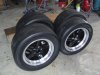
Looks great Russell. Will enjoy seeing your front suspension once everything is put in place. I've tried to determine the size of the tires, but the photo doesn't show it well. Are they 245 & 205 wide?
Hi Terry, the fronts are 205 50 15 giving a width of 230mm and the rears are 245 50 15 giving a width of 270mm. These tyres also give me the diameters as close as for the origional / stance.
One of the reasons i went inboard shocks was apart from giving it a modern twist, ride height adjustment was just a matter of adjusting the push rod length, if my length is out, its just a matter of knocking up new ones.
Cheers
One of the reasons i went inboard shocks was apart from giving it a modern twist, ride height adjustment was just a matter of adjusting the push rod length, if my length is out, its just a matter of knocking up new ones.
Cheers
Attachments
Terry Oxandale
Skinny Man
Looks great! I like the "twist".
Yea! Like the idea of moving the master cylinders right to the front, I've alsio been battling with that. Was about to mock up top hung mounts but that might also work for me.
Cheers
Fred W B
Cheers
Fred W B
Similar threads
- Replies
- 2
- Views
- 427
- Replies
- 8
- Views
- 667
- Replies
- 16
- Views
- 2K
- Replies
- 0
- Views
- 689