Mclaren M8b replica (visual)

Brian
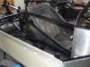
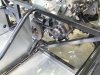
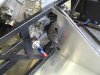
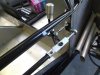
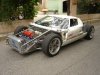
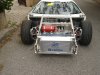
Its finished cars like yours that keep us on target, the buzz of that first drive is also a tremendous feeling of completion and I hope some day that we can get the cars together and show `them` the passion. While waiting, I molded a seat form into the chassis rather than make it out of ally, this will them get a foam lining to closely fit my body shape.
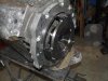
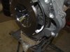
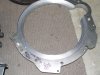
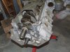
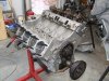
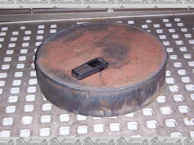
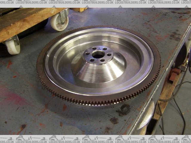
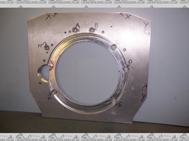
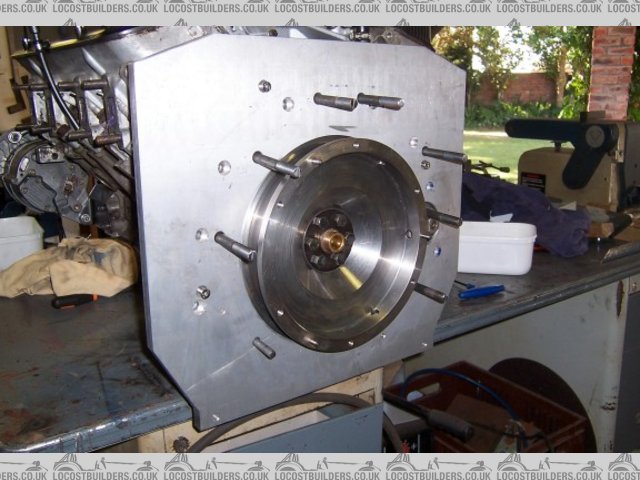
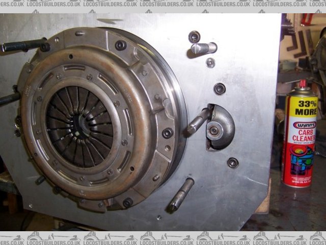
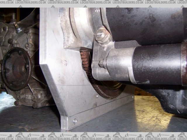
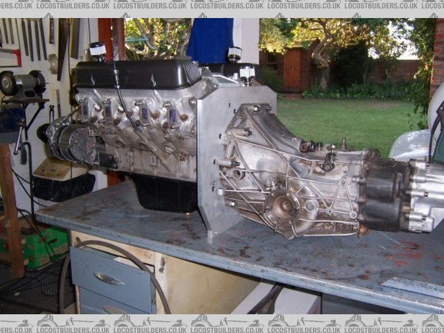
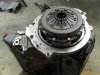
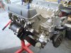
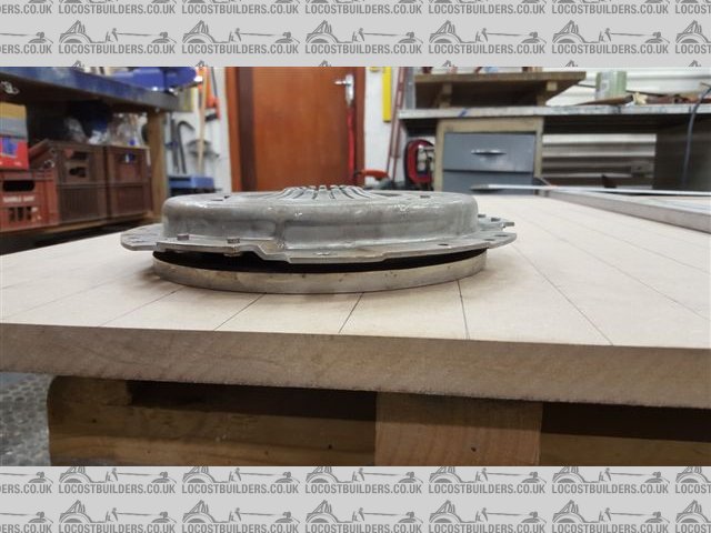
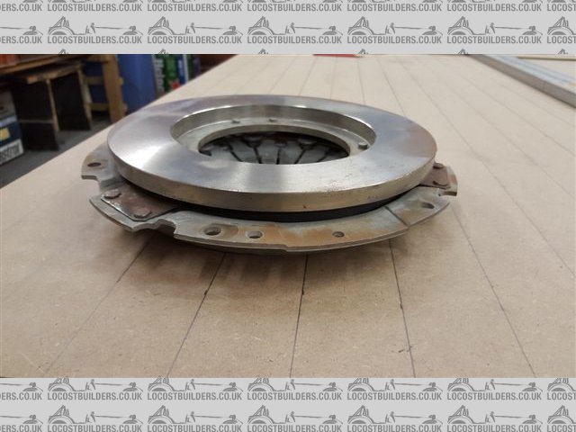
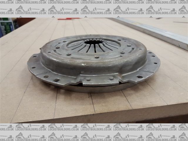
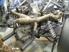
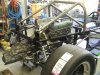
Finally got one of my missing components (flywheel balanced) and after check fitting to the motor, have now turned out the recess in the adapter plate to run the standard Rover ring gear and starter motor. Have started to assemble the motor now as all the bits are now on hand.
Progress will slow for a week or so now as off and away in the motor home for a week or so chasing the sun!
Cheers Russell
 

Attachments

  • DSCF7521.jpg
    DSCF7521.jpg
    166.5 KB · Views: 326
  • DSCF7522.jpg
    DSCF7522.jpg
    131.2 KB · Views: 259
  • DSCF7528.jpg
    DSCF7528.jpg
    268.2 KB · Views: 242
  • DSCF7525.jpg
    DSCF7525.jpg
    160.9 KB · Views: 263
  • DSCF7523.jpg
    DSCF7523.jpg
    178.3 KB · Views: 298
Last few days before `leave` so started on motor assembly, I have used head studs because its much easier / safer to get good torque settings on the fine threaded steel studs versus the coarse alloy threaded bolts in the Rover block. Pulled my head gaskets out of the packet and I see that they are steel, so not sure if my block was surfaced for the composite or if there is any difference in installation ?
Also notice when reading the Rover manual that it said to have the rocker shaft main tube with the notch at the top being left and right handed ? mine have no markings so presume that they can go either way?
The new camshaft went in fine with the only thing missed being the pre lube, its so much harder to add that sticky pre lube when you have to rotate the whole crank set up, any all done now with the new lifters in position
I was surprised at how much tighter the new timing chain and gears were so well worth replacing.
Its a good feeling dragging all these bits out from the cupboard and fitting them...its like christmas.
Cheers
 

Attachments

  • DSCF7540.jpg
    DSCF7540.jpg
    197.6 KB · Views: 246
Nice going Russel.
It looks great.

With your flywheel did you consider running a drive plate for the starter and running a flywheel that looked like a disk rotor.

I know you have it all done and it is what it is, you could have removed a fair bit of mass at the OD.

I know people pick but I am not ,Just curious is all.

Jim
 
Jim
Thanks for that, to be honest...it never occurred to me even though I stripped a Rover auto drive plate to get the ring gear. This is the 3rd one I have done so blame it on habit. Just went and had a look at the crank and yes it would work very easily, you would just have to get the set back of the plate correct to allow proper starter engagement...reasonably simple. Tell you what, if I have any dimension issues when I put this together, I would be tempted to make that change as I still have a Rover auto drive plate.
 
I had clearance issues when I did mine.

The original drive plate stepped up 25mm, towards the gearbox.
this would make my conversion plate thicker.

Issues on mine was the the gearbox bellhousing pattern is smaller than the ring so you have to tuck it underneath.

I had laser cut a 3mm flat sheet then welded the ring gear on just like a drive plate.
I kept the welds exactly spaced and I didnt even get it balanced.
This made the con plate about the same thickness as yours.
By using the original plate It would have been about 15mm thicker plus clearance.

By bringing the plate closer 15mm to the motor all I did was make a 15mm spacer to live under the starter, my starter is on the eng side so it made it easier.

Hope that gives you some hints if you decide that way next time.

My flywheel is only about 12mm-14mm thick at the most.

http://www.gt40s.com/forum/gt40-build-logs/16127-roaring-forties-105-a-4.html
Post 72 will give you a visual on some components.

Cheers

Jim
 
Last edited:
Jim, thinking it thru, the problem would be working from a spacer on the crank to achieve that distance. Any error here would have significant balance issues. A better option would be to turn up the fly wheel at the correct spacing for the clutch face to the selected gearbox and incorporate a flange spaced back from the boss to carry a laser cut ally plate to carry the auto ring gear. (Plenty of auto ring gears which just bolt on are available for nix)
This set up will still require the ring gear to be recessed into the adaptor plate.
In my case, I have pinched about 6mm towards the motor by relieving a small amount of aly in the bell housing mount area. I have also moved the starter motor forward the same amount with a spacer plate that is screwed and spigoted in place. My adaptor plate is 25mm thick and the ring gear recess is 11mm deep with all the major Audi bolts situated in the full plate thickness. If you look at the adaptor pics, you can see what I mean.
Cheers
Russell
 
I did something very similar. I made my flywheel to suit the rover ring gear on the back, and the Audi clutch on the front. My adaptor plate is 16 mm thick, with an 8 mm recessed area for the ring gear. I also moved the ring gear towards the engine, by 12 mm. Also had to relive the block webs somewhat.

The flywheel is 64 mm thick, weighed 7 kg (without ring gear). The wall thicknesses of all areas of the new flywheel are mostly 6 mm, with the conical center section 8 mm thick. The original rover flywheel weighs 14 kg.

Started with this forged blank, okay, that is a huge billet (dia 400mm x 90 mm thick = 90kg), but is was donated.


BLANKJPG.JPG


flywheel1jpg.jpg


flywheel%202jpg.jpg


adaptor%20plate.jpg


plate%20locate%20engine.jpg


clutch.jpg


ring%20clear.jpg


2drivetrain.jpg
 
Fred
Seems there are many ways to achieve the same thing, the pressure plate looks interesting in that its face is almost recessed into the flywheel, what was it from?
Cheers
 

Randy V

Moderator-Admin
Staff member
Admin
Lifetime Supporter
What a truly MASSIVE amount of work on that flywheel! Great job! 90kg must have been a chore to get that hung on the lathe!!!
 
Hi Russell - The clutch assembly is a standard one as listed for the Audi 016. I bought an Audi flywheel to copy the flywheel detail. In effect the flywheel is the Audi detail on the front attached to the Rover detail on the back, with the offset designed to suit the clutch spacing I ended up with in the belhousing.

All this effort is necessary because the Rover ring gear does not fit in the Audi bell housing. If I did the conversion again, I think it would be easier to just cut down both a Rover bell housing (it bolts onto the Rover gearbox) and Audi transaxle case and weld them together, with a plate between the two pieces to make the connection easier. It would not look as neat in the end though.

Hi Randy - Thanks, but I can't take credit for actually turning up the flywheel. The machining was organized by a friend who owns a large engineering concern, with the right CNC mills and lathes. He charged me something to do it, but I think it was a very fair price.

The adaptor plate, on the other hand, was cut from a 16 mm plate by another friend who has a large CNC router usually used for cutting wood and perspex. I did the chamfer at the starter motor by hand with a file.

Cheers

Fred W B
 
Last edited:
Fred
That clutch plate looks interesting in that it appears to be recessed relative to its bolt pattern.
Last thing I did before I went on holiday was to drop the gearbox onto the motor to ensure that it fitted...otherwise I would have spent the whole time wondering. Happy to say that it fitted like a glove and all appears correct and workable. On return today, I have correctly sized and fitted all the bolts, lock tightened and wired so they should stay put. Next task was to carefully lift and get the motor horizontal to insert in the chassis. Again happy to say that all went well and its back in the frame ready to be fitted off.
Work for a few days then some more shed time.
Cheers
 

Attachments

  • DSCF7545.jpg
    DSCF7545.jpg
    146 KB · Views: 272
  • DSCF7542.jpg
    DSCF7542.jpg
    145.2 KB · Views: 232
  • DSCF7543.jpg
    DSCF7543.jpg
    140.4 KB · Views: 292
  • DSCF7541.jpg
    DSCF7541.jpg
    185.3 KB · Views: 253
Thanks for that Fred, yes I can see that the dimensions are different from what I would call a standard pressure plate, should I do another one I will surely look at that option...along with running the ring gear on a flex plate as both of those will drastically reduce the size and weight of the flywheel.
Cheers Russell
 
Bit more progress, exhausts wrapped and fitted, alternator on with belt, gear change sorted, roll bar completed and fitted ready for powder coating. Things are a little tight around the oil outlet to the remote filter and the water inlet / outlet where the pump was previously mounted is also close but should be right. I had juggled dimensions on this chassis and could have done with 25mm longer in the engine bay. Next week I will start fitting up the inlet manifolds with the 40mm Del Orto carbs. One thing changed on this roll bar set up is the rear brace bars are parallel to enable the rear enging cover to be able to tilt up.....thats the plan.
 

Attachments

  • DSCF7640.jpg
    DSCF7640.jpg
    193.4 KB · Views: 293
  • DSCF7637.jpg
    DSCF7637.jpg
    158.8 KB · Views: 277
  • DSCF7639.jpg
    DSCF7639.jpg
    149.4 KB · Views: 262
  • DSCF7638.jpg
    DSCF7638.jpg
    129.3 KB · Views: 237
  • DSCF7636.jpg
    DSCF7636.jpg
    227 KB · Views: 337
Hi Russell, great progress mate. This being the second car does that make things a lot more straight forward as you know what you need parts/design wise or is there a lot of little changes that we don't really appreciate. You seem to be moving so fast it's like you have it all pre planned and just go for it or is it a lot more hours in the shed than we see. I sure wish mine was progressing this quickly. Love the up dates.

Cheers Leon.
 
Leon, yes doing it for the second time does have its advantages but it also has its traps as you tend to get , 'smart' and make changes that can have repercussions.
Now that I am semi retired I do have much more shed time so progress is faster for definite.
Still have to be careful and get things done in the right order.
Just been setting up the inlet manifolds tonight so the motor will start to look the part soon.
Cheers
Russell
 
Anti roll bars. (Front)
Does anybody have twist? Or torsion figures for chrome moly tube. I am planning on using tube inside a tube with attached arms and would like some pointers as to what diameter / gauge tube to use for the inner. Otherwise I will use adjustable blades at each end if that info is available.
Any help would be appreciated.
Cheers
Russell
 
Hello Russel,

You will see on the attached pictures what I installed as front anti-roll bar on my Gt40 ; not exactly a can-am and what you plan to make.... but may give some ideas...

*The bar is a simple tube 25 OD, 2 mm thick , 25CD4S

*800 mm wide

*Arms are from 2017 A ally - 220 mm long and 10 mm thick

*I get approx 150 lbs/inch at end of arms ( adjustable of course)

It is working so far, on (moderate...) track use and non-slick tires .

If you plan to use a double bar, you will probably have to go to larger OD and thickness tubes in order to achieve the stiffness you need on your high performance chassis ...

Rene
 

Attachments

  • gt40 208 road lateral.jpg
    gt40 208 road lateral.jpg
    100.8 KB · Views: 292
  • gt40 209 road front.jpg
    gt40 209 road front.jpg
    102.8 KB · Views: 239
Thanks Rene
That gives me some base line to start from, I was thinking of using blade type arms but feel that is starting to get difficult because I can not make them.
Regards
Russell
The tube you used is 25mm cold drawn ..what does the 4s stand for?
Mild steel or crhome molly
 
I am not a metalurgic expert ...but this is what I understood :

The 25CD4S designation has a US AISI/SAE equivalent which is 4125 ; it seems that the close designation 4130 is more common in US.

Both are typical chromolly steels, performing more than mild steels.

CD 4 stands for 1.2 % Cr , 0.3 % Mo, and 0.8 % Mo

The S stands for "Soudable" in french ...which means weldable ...

René
 
Back
Top