McLaren replica build base on a Manta

Terry Oxandale

Skinny Man
Yeah... But, after discussing this with several other members, the use of stainless plus insulation makes a big difference. Based on another car I used to own which had the radiator air exit out the top of the "hood", my main heat issue may be the hot air over and around the windshield rather than the tubes.
 
Terry,
I'm going to use aluminum tubes and they go in the side pods. I may have the same problem as you around the windshield. Both our cars bodywork was designed by the same guy and fabbed by Specialized Moldings out of the UK. I going to do some work around the house this week and start digging in again now that the weather is getting better.
Dave
 
Hi Terry, you mention the hot air from the front mount radiator exiting out the front hood. This was a major problem for the open Can-Am cars and a lot of things are written about this in the McLaren books I've read, there are stories of Denny and Bruce driving through the pits Just so the crew could tip a bucket of water over them. Denny gave great thanks when they went to hip mounted radiators on the M20, He said , If there was no performance gain Mechanically, the permance gain of the Driver alone was worth it. I wouldn't think it would be quite as servere with a closed in car but I know with my job driving around in the desert of the Middle East the heat that radiate's through the wind sheld heat the glass to point where you can't touch it. Are you having A/C in the car??
Love you work so far and always look for your up dates. Cheers Leonmac.
 

Terry Oxandale

Skinny Man
My hope is that 600-800 HP of heat will not need to be dissipated continuously whilst I drive the car. Track days will be limited, and the street will not require a lot of heat dissipation. So we'll see.

Today I finally fitted up the Outlaw 3000 series calipers to the rotors, so I'm nearing a point in the build where everything will be removed from the frame, the frame gets media blasted and painted, and then I start bonding panels and start a final assembly of bits and pieces (the fun part) before the fiberglass work begins.
 
Terry,
What are you going to use for the park brake? Are you going to add another single piston caliper with with master cylinder on the park brake, or something mechanical with cable.
Dave
 
Terry,
I am going with Wilwood's and the mechanical parkbrake caliper. I may have to run a vented disc on the rear to get them to work.(disc thickness) I have solid right now. You can run a single piston caliper some have the arm if you want to do a cable setup. Here is a pic of setup.
Dave
 

Attachments

  • Picture (Small).jpg
    Picture (Small).jpg
    30.4 KB · Views: 634

Terry Oxandale

Skinny Man
Thanks Dave. I like the idea of cable better than hydraulic, but the cable is less flexible from an installation point of view, what with all the business going on back there already.
 
Terry,
That was a pic of a Lambo setup. I think here to pass the safety test I will need mechanical park brake. Two reinforced flex cables from the calipers snapped into a piece of angle iron mounted on the floor. A single plate connecting the two. Hole in the center for the threaded park brake handle flex cable. Another mount for the flex cable from the park brake a good six inches from the other pick up. Coil spring over the threaded attachment part of the handle. Some oval lock nuts. You can also use wire rope with compression fittings on the end and C-clips and do a large loop and have the park brake rod with a hook in the center. this helps if the flex cables from each caliper is not long enough. You will need some guides for the loop.
Dave
 

Terry Oxandale

Skinny Man
ITB set-up

I'm Pulling my ITB set-up post back to the Manta build post. In this update I've added the throttle linkage.
I had fabricated a throttle operating wheel for my Webers a couple of years ago. So it was a simple decision to pull it off the Weber intake, fabricated a new taller tower to raise it up to an operating height level with the ITBs, and link it all together. The first photo shows the tower mounted onto the valley cover. If I seal the tower base sufficiently (a simple gasket should do the trick), I can use the tower as a MAP vacuum chamber. McMaster-Carr has some pretty neat shaft couplers. It will be a bit of a hassle to synchronize them at first (no adjustment screws between ITBs), but once done, it should be good for a while.

standard.jpg


standard.jpg


standard.jpg
 
Last edited:

Terry Oxandale

Skinny Man
Header smeader

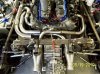
I'm waiting on more tubing so that I can put this portion of the project to rest.

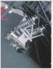
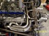
Biggest challenges? Cant go over the top of the transaxle due to the rear body panel's location within a couple of inches of the top of the transaxle (which means 180º headers of equal length is VERY challenging due to the longer crossover tubes), framing that prevents much in the way of lateral space, and the the LS motor's coil packs (avoidance of heat from the tubes).

So I'm moving the coil packs down under the tubes to the framing adjacent to the block, and working within a narrow range of space over the framework, but under the body panels, which means a pancaked arrangement that still is constrained by the trailing arms. LORD, 4-into-1 would have been SO much simpler.

So in the end, I'm about 2" shy of "equal length" on a couple of sets.
 

Attachments

  • ScreenShot009.jpg
    ScreenShot009.jpg
    89.4 KB · Views: 622
  • ScreenShot014.jpg
    ScreenShot014.jpg
    94.2 KB · Views: 569
Terry,
Your throttle linkage looks very similar to the TWM setup that I am using. even your throtle body connections look the same. You might look to their site for any problems you might run into.

Bill
 

Terry Oxandale

Skinny Man
Thanks for the tip Bill. I'll go take a look-see. Earlier in the build, Kelly commented on potential issues with a long single shaft on each bank, so I saw these .8º misalignment, zero back-lash shaft connectors with a relatively high-temp spider and thought I'd try them out.

Ox
 
Last edited:

Russ Noble

GT40s Supporter
Lifetime Supporter
Ox,

Nice work as always. Everything on these cars gets more difficult as you use up the existing space! And a McLaren is probably worse than a GT40. Like your intake setup too.

Cheers,

Russ
 
Last edited:

Terry Oxandale

Skinny Man
Headers finally tacked up

Finally finished the "shape" of the headers, but final welding is still in order. Midway through this process I thought I had thrown in the towel and diverted to the path of 4-to-1 instead of the 180º design. I'll never do this design again (onless I can put the collectors up and over the transaxle). Just too much time and work for what...3 or 4 HP? In order to clear the low-hanging rear bodywork, and the close framing on the sides of the motor, I had to "pancake" them out the side of the motor.

standard.jpg


standard.jpg


Then I relocated the coil packs down under the headers to avoid the high heat of the headers being just under the coils using some 1/4" stainless rod, some spacers, and an aluminum bracket bolted to unused bosses on the side of the block.

standard.jpg


standard.jpg
 
Last edited:
Back
Top