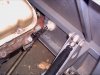
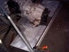
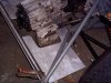
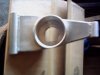
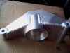
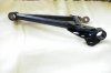
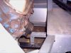
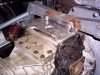
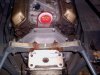
Motor is re-set and mounted.
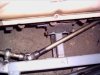
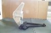
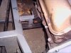
Had to move the crossmember forward 2", which reflected the difference between the ZF bellhousing and the Porsche setup I originally intended. The axle centerline on the Porsche box is also closer to the motor so the change was necessary.
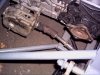
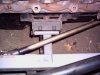
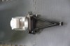
I managed to get the motor centered within 1/16" side to side, well within tolerance.
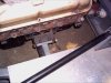
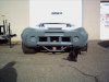
Everything is level both ways, and I can now go and relax and enjoy some Christmas dinner.
Merry Christmas
Phil
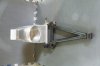
Had to move the crossmember forward 2", which reflected the difference between the ZF bellhousing and the Porsche setup I originally intended. The axle centerline on the Porsche box is also closer to the motor so the change was necessary.
I managed to get the motor centered within 1/16" side to side, well within tolerance.
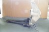
Everything is level both ways, and I can now go and relax and enjoy some Christmas dinner.
Merry Christmas
Phil
 :
: