My Scratch Built Project

Pete:
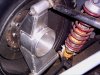
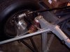
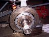
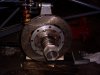
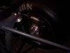
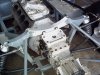
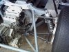
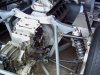
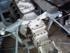
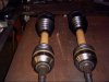
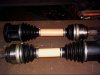
Bearings, flanges, and outer CV's are Mustang Cobra units. The halfshafts are also from the Cobra. The inner CV's I have fit up to my ZF gearbox, as the Cobra halfshafts are a bit longer all that was needed was a shortening and some re-splining to make the axles.
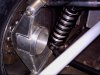
Thanks for your comments on the uprights. I will be tuning them up soon for the final install, and will post those photos as I progress.
Just a note:
I found the Cobra units on Ebay, and they were about 1/3 the price if bought from a dealer or supplier.
The same flange and bearings are used by the T-bird, but the flange is drilled on a metric BC, the Cobra flanges are available in the Ford Motorsports catalog drilled 5 on 4 1/2" BC.
Checked out your build...looking good.
Cheers
Phil
 

Charlie M

Supporter
Phil,

How did you mate the Mustang Cobra inner CV to the ZF gearbox? Doesn't it have a splined shaft rather than a flange? I'm looking to use the same setup but mated to an Audi transaxle.

Thanks,
Charlie
 
Daryl:
I had a set of molds made around existing pieces, the chassis is my design and is a spaceframe. Thanks for your positive comments.

Charlie:
Outer CV's were no problem, the inner was done by cutting the Cobra halfshaft and welding in a spline to accept the inner CV joint. The Cobra shafts are about 1 1/2" diam. Very strong, and it was easy enough to weld in the correct spline which conveniently hides under the inner boot giving a smooth look with no visible connection.
I would think the same would be possible with the Audi setup. I found the shafts on Ebay, NOS at much cheaper cost than dealer.
Also, there are silicone inner boots available from Dorman pretty cheap, if memory serves me about $15 for the pair.
Cheers
Phil
 

Charlie M

Supporter
Phil,

What did you use for an inner CV joint? Do you have any pictures of the setup and modification?

Thanks,
Charlie
 
Charlie:
I should have included that in my post. The inner CV is from the same shaft. I simply cut the splined shaft off the inner CV. These are Tri-pot units with about 2" of plunge as the outer CV has no lateral movement available.
My ZF has flanges to take a u-joint type yoke, and I machined a disc from 4340 round stock, drilled and tapped it for the holes in the flange, the bolts enter from the inside and thread into the disc.
The end of the tri-pot joint was machined with a small boss that hub centers to the disc and welded. The bolts can easily be safety wired and don't foul the case on the gearbox.
I will take some photos if you need them and post.
Cheers
Phil
 

Charlie M

Supporter
Thanks for the info Phil, I'll have to take some measurements first but I should be able to do the same for the Audi. A photo or two would be great.

Great build, BTW.

Thanks,
Charlie
 
Been quite while since my last post, glad to be busy but it gives me less time for my projects.
I mounted both fuel tanks this past week, and next is the paneling above the tanks and inside the cockpit. Fuel sender works well and hookup to the fillers and finishing the paneling inside the cockpit in that area is next on the schedule.
The tanks have tabs on top that limit movement, but are held with stainless straps that are lined with neoprene and the tanks fit well with no movement.
The bolts for the straps are countersunk at the top, enabling paneling to be fixed on top with no interference, and the strap bottoms are bolted thru the chassis rail holding the tanks approx 3/8" above the chassis bottom.
Here are some photos of the mounting.
Cheers
Phil
 

Attachments

  • LS front strap 4-2011.jpg
    LS front strap 4-2011.jpg
    199.6 KB · Views: 389
  • LS rear strap 4-2011.jpg
    LS rear strap 4-2011.jpg
    204.4 KB · Views: 380
  • RS mounting detail.jpg
    RS mounting detail.jpg
    200.5 KB · Views: 403
  • Tank detail 5.jpg
    Tank detail 5.jpg
    198.5 KB · Views: 438
  • RS filler neck detail 4-2011.jpg
    RS filler neck detail 4-2011.jpg
    198.8 KB · Views: 388
Started paneling the two valance tops above the tanks. Ran the panels thru the beader and added my access panel for the sender. I wanted to have access to the sender to avoid having any problems if I needed to remove it or had wiring issues, which I don't anticipate but there is access just in case.
Cheers
Phil
 

Attachments

  • RS valance2 4-11.jpg
    RS valance2 4-11.jpg
    201.5 KB · Views: 313
  • RS valance3 4-11.jpg
    RS valance3 4-11.jpg
    202.4 KB · Views: 299
  • RS valance4 4-11.jpg
    RS valance4 4-11.jpg
    200 KB · Views: 265
  • RS valance 4-11.jpg
    RS valance 4-11.jpg
    196.4 KB · Views: 293
Quite a while since my last post, but progress nonetheless.
A while ago I posted photos of the new uprights I had intended to use as I was not happy with the previous design. The problem was clearance for the outer CV, so back to the drawing board as the saying goes.
Here are some photos of the build process of the uprights and the final installation. Also updated the lower inverted wishbones and had them powder coated. The new rotors are also mounted and next step is calipers and all should be OK.
Cheers
Phil
 

Attachments

  • Picture 006.jpg
    Picture 006.jpg
    201.1 KB · Views: 380
  • Picture 007.jpg
    Picture 007.jpg
    199.6 KB · Views: 353
  • Picture 003.jpg
    Picture 003.jpg
    194.9 KB · Views: 357
  • Picture 010.jpg
    Picture 010.jpg
    196.1 KB · Views: 345
  • Picture 012.jpg
    Picture 012.jpg
    204.3 KB · Views: 334
  • Picture 018.jpg
    Picture 018.jpg
    199.2 KB · Views: 338
  • Picture 025.jpg
    Picture 025.jpg
    200.9 KB · Views: 343
  • Picture 026.jpg
    Picture 026.jpg
    199.2 KB · Views: 347
  • Picture 029.jpg
    Picture 029.jpg
    200.2 KB · Views: 357
  • Picture 035.jpg
    Picture 035.jpg
    199 KB · Views: 367
  • Picture 036.jpg
    Picture 036.jpg
    202.1 KB · Views: 446
  • Picture 038.jpg
    Picture 038.jpg
    200.2 KB · Views: 379
  • Picture 039.jpg
    Picture 039.jpg
    197 KB · Views: 367
Hi Phil,
really, really nice work. It's got me know thinking about replacing my fabricated steel rear hubs with something like yours
keep up the good work
Andy
 
Thanks Andy, wish I had more time to stay on it but times being what they are I just plug away. I was able to cut the upright weight almost in half, and these pieces are 1/4" 6061 alum. They are welded inside and out, except for the rear cover, and the bearing mount is a machined piece that took some work but I think it was worth it.
Russ, I always appreciate your chiming in, I will have you know I followed your rule of the 4 iterations to the letter and here is the result.
Also, the lower wishbones are fully setup with spherical bearings, and the bottom of the uprights have provision for setscrews to keep the cross shaft from rotating in the upright.
I fabbed the lower cross bolt from 4340 rod, threaded both ends just enough to clear the bearings and added a castle nut on both sides.
I think it will work out nicely.
Cheers
Phil
 
Some small amount of progress.
Finished the rotor mount hats and mounted the rotors. They are 1.25" X 11.75" diam. lightweight units. The lateral runout is less than .001 which I am very happy with, so it looks like my next step is mounting the calipers and I will post photos of that as soon as it is complete.
Cheers
Phil
 

Attachments

  • Picture 041.jpg
    Picture 041.jpg
    199.8 KB · Views: 337
  • Picture 043.jpg
    Picture 043.jpg
    198.7 KB · Views: 270

Terry Oxandale

Skinny Man
Quite a while since my last post, but progress nonetheless.
A while ago I posted photos of the new uprights I had intended to use as I was not happy with the previous design. The problem was clearance for the outer CV, so back to the drawing board as the saying goes.
Here are some photos of the build process of the uprights and the final installation. Also updated the lower inverted wishbones and had them powder coated. The new rotors are also mounted and next step is calipers and all should be OK.
Cheers
Phil

Phil, will you need to treat (harden, etc) the uprights after the last bit of welding is performed. I really like what you've done, and would like to repeat this myself, but I don't have enough experience in aluminum sheet construction to be confident in the strength after it's all put together.
 
Terry:
Sorry for the late reply, been busy on a site job.
I heated the uprights to 600 F and quenched them, I think they are very strong. Also the material is welded inside and out, and all of the joints are either V-cut or fillet so I'm not worried about the strength factor.
I took one of the prototypes I made and put it in my press face up, since I had welded a lot of it outside the fixture the dimension top to bottom had shrunk about 1/8", it took about 20 tons of pressure to spread the bottom, and I never got the dimensions to move enough to fit it back into the fixture.

Meanwhile here is a couple of photos of my final rear shock mounting, and everything moves well with no binding...next are calipers and hopefully my motor will be here soon so I can fit it up to the gearbox and start fabbing the exhaust and do the plumbing and electrical for the back of the chassis.
Cheers
Phil
 

Attachments

  • L R Shock detail.jpg
    L R Shock detail.jpg
    200.8 KB · Views: 303
  • R R shock detail.jpg
    R R shock detail.jpg
    198.6 KB · Views: 258
Last edited:
Finally got back to the 40. Have been busy with work and other stuff, but things are happening now.
A friend of mine stopped in last week and thought he would like to contribute to my project so with a few measurements I suddenly had a brand new billet crossmember, kind of fancy, but it looks great on the chassis.
Half shafts are finally complete, and I got my gearbox back with ring and pinion flipped and oiling mods done.
Waiting now for a flywheel and then we can mate up the gearbox to my new motor...photos of that later...and start setting up the exhaust.
More to come.
Cheers
Phil
 

Attachments

  • Picture 008.jpg
    Picture 008.jpg
    202.7 KB · Views: 345
  • Picture 011.jpg
    Picture 011.jpg
    203.8 KB · Views: 339
  • Picture 012.jpg
    Picture 012.jpg
    201.9 KB · Views: 343
  • Picture 007.jpg
    Picture 007.jpg
    199.5 KB · Views: 357
  • Picture 015.jpg
    Picture 015.jpg
    196 KB · Views: 331
  • Picture 014.jpg
    Picture 014.jpg
    196 KB · Views: 309
Looks great Phil!

I love to check out the work of a true old school craftsman.

Glad to see you are back at it and as always I very much enjoyed chatting at Carlisle.

Best,
Scott
 
Thanks Scott;
I wish I could progress a little faster. I will post a few photos of my motor tomorrow, and a better resolution photo of that cross member.
Cheers
Phil
 
Back
Top