Norfolk Tornado

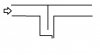
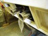
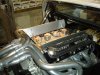
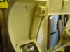
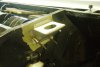
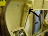
I’ve not seemed to achieve much recently, but it is still progressing very slowly. The N/S NACA duct has been opened up and a duct made to connect it to the heater matrix as a fresh air duct. I used some PVC foam to create the desired shape and after the 2 layers of fibreglass had cured it was dug out to create the desired duct. The O/S duct has been opened up and a short duct made to give the impression of a functional duct. I’ll probably do the same for the centre duct, but this will be left until spring next year as it now too cold for glass work in an un-heated garage. I’ve also added core matt underneath the front panel to stiffen it up and a foam beam has been glassed in on the lower edge of the radiator opening, again to add some much needed additional stiffness.

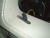
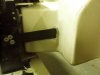
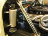
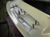
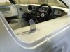
I finally fitted up the door locks & remade the release levers for the doors, as I think they look aesthetically more pleasing. I know they’re not original, but why use 4 mounting screws for the base plate, when only 2 are needed! However I think the levers will have to removed for the IVA test or remade, as they don’t meet the min radius requirement of 3.2mm – it’s difficult when it’s only 3mm thick! Any ideas?

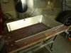
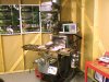
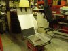
Realising I’ll need to sort out the seats, I dug out the pair I’d started building back in 2008 and have that have been gathering dust ever since.
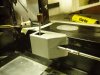
Discussions with the trimmer highlighted that my side foams aren’t stiff enough and would eventually collapse. He also recommended that edging strip is used around the edge of the frame to prevent the leather chafing on it. The black pad is the lumbar pad, which has yet to be glued to the frame. His workload means that he can’t start until February, but there’s plenty of other things to keep me busy
Regards
Andy
 

Attachments

  • duct.JPG
    duct.JPG
    134.1 KB · Views: 616
  • duct 2.JPG
    duct 2.JPG
    93.5 KB · Views: 638
  • release lever.JPG
    release lever.JPG
    144 KB · Views: 620
  • seat.JPG
    seat.JPG
    152.2 KB · Views: 684

Ian Anderson

Lifetime Supporter
Almost as if it's Pantomime season "It's behind you"
So from memory that means it does not to be radiussed.

Sort of like Seat Belt mounting bolts also do not get radiussed

Well it worked at SVA stage!

Ian
 
The N/S NACA duct has been opened up and a duct made to connect it to the heater matrix as a fresh air duct. I used some PVC foam to create the desired shape and after the 2 layers of fibreglass had cured it was dug out to create the desired duct.


Hi Andy,

I have done the same thing with my ducts for fresh air, but have not worked out how I am going to connect the far end to the heater matrix, how are you intending to do this?

Great build by the way.
 
I disagree, I think they are not exempt

Area 1 Exempt zone: is the dashboard area aorund the steering wheel and the area up to the A pillar

Area 2: As the handles are over the 150mm plane of the seat base, then they would be tested using the 165mm sphere and therefore be in the specified zone.

As they project more than 3.2mm, then they have to have a radius edge of 2.5mm, not 3.2mm as you stated Andy. I assume you have read the door handle as being part of the roof structure, where it does state that it needs to be a radius of 3.2mm.

FWIW - I believe SGT cover their door handles with heat shrink
 
Hi Brett,
I was also under the impression that they were not exempt, therefore I raised the issue. I was erring on the side of caution using 3.2mm as a minimum instead of 2.5mm and I’d rather plan for it to be included than have a fail on the day due to a mis-interpretation of the rules.

I like the idea of using heat-shrink, the other method I’d considered is to use Plasti-coat; the stuff used for tool handles etc.

Hi Nick,
I wasn’t going to connect it up to the far end of the blow motor. One end should be sufficient; the rest will be just re-circulated.

Regards,
Andy
 
saxoncross;390872 [FONT=Arial said:
Hi Nick,[/FONT]
I wasn’t going to connect it up to the far end of the blow motor. One end should be sufficient; the rest will be just re-circulated.

Regards,
Andy

Hi Andy,

Apologies but I'm not sure you understood my question. I was wondering how you intended connecting the arrowed end in the picture below through the clip rear and bulkhead into the cabin.

I assumed that is what you are intending to do, but may have got that wrong. :(
 

Attachments

  • duct1a.jpg
    duct1a.jpg
    126 KB · Views: 508
Hi Nick,
sorry I should have make it a bit clearer. A soft foam seal will between the moulded duct & the fabricated elbow. Internally a small length of ducting will go between the elbow & the fan inlet
Regards
Andy
 
I can't find a diagram to show it but you want to change the direction of the airflow faster than the inertia of the water can cope with. At its simplest this is something like this (sorry for the crap mspaint image)

attachment.php


You probably would find it easiest to re-use a motorcycle ram-air duct though.
 

Attachments

  • Water_separator.jpg
    Water_separator.jpg
    12 KB · Views: 1,776
Hi Brett, David
It will be something like what David has sketched. The vertical plate will be the current wheel arch panel and the drain will be a notch in lower edge of the elbow I fabricated
Regards
Andy
 
Happy New year to you all. A few more jobs completed over the Christmas period:
  • Silencers installed with IVA friendly tail pipe trims
  • IVA’d the door release catches (built up with electrical tape & then sealed with heat shrink)
  • Cover for the gearshift mechanism, yet to be powder coated black. Again for the IVA, but it might be retained with a polished gate surround, not decided yet. Also found an old wooden gear knob which looks more period and I turned down the gearlever stem as it looks too chunky
  • Door check straps have been fabricated using an old strap off a laptop bag
  • Made the ‘turkey pan’, although mine only has 3 sides & no bottom! It’s made from 1.5mm ally with rolled edges and 2mm ally used for the brackets
  • And finally some cheap Ebay sill stripes, prior to it be painted – it looks better already, as it will be a while before it gets painted….
Regards
Andy
 

Attachments

  • tailpipes.JPG
    tailpipes.JPG
    159.4 KB · Views: 537
  • release latch.JPG
    release latch.JPG
    152.6 KB · Views: 489
  • shroud.JPG
    shroud.JPG
    143.1 KB · Views: 606
  • door strap.JPG
    door strap.JPG
    151.5 KB · Views: 563
  • turkey pan 1.JPG
    turkey pan 1.JPG
    136.7 KB · Views: 616
  • turkey pan 2.JPG
    turkey pan 2.JPG
    135.5 KB · Views: 539
  • stripes.JPG
    stripes.JPG
    136.9 KB · Views: 618
Hi Andy

Just sorting out my dash and need to fit a hazard light button, and as always, looking at the AG40 for inspiration! Do you know if IVA require a minimum size of button? Can I ask, what are the silver rotary knobs for on your dash?

Regards

Keith
 
Hi Keith,
as far as I know there is no minimium sizes for any of the switches. I used a Durite 048450 switch and can provide a suitable wiring diagram if needed. Also if you use any LED indicator or repeaters, the std Lucas flasher module won't work and you'll need an electronic one.
The 2 rotary knobs are for the heater/demist. One is the fan speed and the second controls the coolant flow to the heater matrix
Regards,
Andy
 
Last edited:
Very slow progress, recently. I’m currently recovering from an operation on my wrist which has stopped all major work and I’ve been distracted by my latest purchase – a milling machine.
It’s a Taiwanese Bridgeport clone, which was bought at give-away price as the variable speed head unit was broken, which turned out to be nothing more than a sheared roll pin and the digital read-outs weren’t working. After rebuilding the head unit and a major re-wire so it now runs from on 240V Inverter (it’s got a 440V 3-phase spindle motor & a 110v transfer bed feed) I’ve been fiddling with it and making bits on it, mainly tooling bits. Having not touched one for over 30yrs it’s been an interesting learning curve.

A few bits on the ’40. The oil catch tank has been fabricated and installed. The cam covers has now been changed over to studs, as the original screws I’d purchased made it difficult to located the gasket during assembly. Also the seats have gone to the trimmers and should be back next month

I was never very happy with the in-fill panel I made previously to get the screen demister to work properly, especially after I’d added a fair amount of body filler to fill in the some of the voids. The new solution is much simpler and with its smaller opening will keep the air velocity up. The original moulding is effectively a diffuser, slows down the air, giving poor demist performance. I’m not saying what I’ve done is perfect, but it can’t make it any worse!

Regards
Andy
 

Attachments

  • Mill.JPG
    Mill.JPG
    147.5 KB · Views: 485
  • catch tank.JPG
    catch tank.JPG
    132.6 KB · Views: 528
  • Demist.JPG
    Demist.JPG
    170.5 KB · Views: 548
Back
Top