Norfolk Tornado

Thanks for the feedback guys. I have seen the light flickering at the end of the tunnel on the odd occasion and I’m aiming it to get it IVA’d later this year
Regards,
Andy
 
Andy, I know the feeling. Been there, done that, got the T-shirt. I hope you really are seeing the daylight and not the on comming train:lipsrsealed::thumbsup:

Bill
 
There’s currently very little to show for the last month’s work. Since the spider is now installed, panelling of the interior rear bulkheads has been completed. The engine bay panels will be added once I’ve confirmed there’s no last minute changes required to the wiring (on my build, as I changed the bulkhead structure for a integral roll bar, I’ve a couple of void sections either side of the engine access panel with the wiring & sound proofing in). The dash is going in for the last time, although it already been out 3 times since I was under this belief!
The rear clam has also been painted on the inside and the heat-proof mat added. I also had some more machining done on the rear clamp brackets (edges bevelled & bolt holes pocketed) before a quick polish & a refit.
Also added a few notes on the car to comply with the IVA regs

Regards,
Andy
 

Attachments

  • Rear Bulkhead.jpg
    Rear Bulkhead.jpg
    186.4 KB · Views: 696
  • Label 1.jpg
    Label 1.jpg
    166.8 KB · Views: 625
  • Label 2.jpg
    Label 2.jpg
    170.5 KB · Views: 570
  • Dash.jpg
    Dash.jpg
    194.8 KB · Views: 707
  • Hinge.jpg
    Hinge.jpg
    185.1 KB · Views: 627
  • Rear Clam.jpg
    Rear Clam.jpg
    215.1 KB · Views: 692
Andy, looking good, you've done a great job. What did you use to stick the matting to the inside of the rear? I bought some similar matting for use there too. K
 
Don't forget to use some edging tape around the fireproofing it will tidy up the edges 100 percent , car builder do this 1 inch wide or demon tweeks 2 inch wide its cheap and finishes it of a treat.
 
Hi andy, if you car runs like mine you won't need to cover the exhausts it just don't get that hot, trust me I have been driving to work in the Mini heat wave were having down south here and the water temps dont go over 90 deg.
Its Always nice to see the exhausts
Looking good mate, light at the end of the tunnel !
 
Hi Keith,
It’s reassuring to hear that your car’s running OK in these current high temperatures. What’s the cockpit temps like, I can’t remember if your car is fitted with A/C?
Regarding the build, I did use some of the edging tape you recommended, a bit fiddly, but it does finish of the exposed raw edges nicely.
Regards,
Andy
 
Not a lot to show at present, mainly small jobs & bolting bits on & torqueing the suspension up

The engine & trans are now filled with oil & dipstick tube set at correct level. I’ve had the oil pressure up by running the oil pump with a jack shaft on an electric drill. It helps to spin the pump the right way! (anti-clockwise for reference). It has highlighted that the pressure gauge works, but I’ve managed to wire up the low pressure warning light the wrong way round, so it looks like the dash has to come out again to fix it!

The other news is that I’ve had the ECU connected and it talks to the laptop and reads live data from the sensors (air, coolant & TPS), hence the separate request

Regards,
Andy
 
Again, not a lot to show, but slowly working through a lot of the small items needed for the IVA, including:
  • Front & rear screens fitted
  • Compliant wing mirrors
  • Edging on door internal edge to achieve min edge radius
  • Crash pad fitted to steering wheel
  • I rewired the rear fog lamp using a latching relay, so that it goes off automatically when the lights are switched off (new IVA requirement for this year)
  • Small plates added next to filler necks to prevent fuel spilling into front area. As it can be argued that the front is a luggage space and fuel has to be kept out of the cabin & luggage areas. It’s a bit pedantic, but its easy to fix now than fail on a simple point
  • Again, not sure if its needed, but I added a mesh to the lower front opening
Regards,
Andy
 

Attachments

  • rear shot.JPG
    rear shot.JPG
    112.8 KB · Views: 461
  • interior.JPG
    interior.JPG
    139.1 KB · Views: 511
  • fuel  weir.JPG
    fuel weir.JPG
    112.9 KB · Views: 557
  • front grille.JPG
    front grille.JPG
    111 KB · Views: 603
  • door trim.JPG
    door trim.JPG
    96.1 KB · Views: 531
  • Door mirror.JPG
    Door mirror.JPG
    130.5 KB · Views: 575
Hi Keith,
I’m been waiting to get the radiator back from the fabricators, who finished me the stone guard, which I collected yesterday. Once refitted, I can get the engine started. Then it will go on a rolling road to get a base calibration and then it can go for it’s IVA. Hopefully in the next couple of months
Regards,
Andy
 

Attachments

  • rad 1.JPG
    rad 1.JPG
    134.9 KB · Views: 427
  • rad 2.JPG
    rad 2.JPG
    140.6 KB · Views: 418
Hi Andy,

Your stone guard is a brilliantly simple and effective idea. Do you have an air con condenser between the radiator and stone guard? Did you find a fabricator in Norfolk?
Cheers, Neil
 
Hi Neil,
Glad you like it and yes, the condenser’s sandwiched between the two. I believe in sourcing locally where possible and the fabricator is ex-Lotus and based in Wymondham, which means I can pop out at lunchtime to see him. He does all my alloy welding and the difficult bits beyond my skill level. I can pass ion his details if you’re interested.

Regards,
Andy
PS where’s your build log……….:shy:
 
Engine Start-up!
This was planned for last night and I had a few friends over to help & hinder…
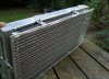
Having an electric waterpump makes filling & bleeding the system really easy, so this was quickly ticked off the list.

The fuel system was then jury-rigged from a jerry-can, but utilising the car’s HP pump, as at this stage I didn’t want to run the full system. The first issue we found was that that the ECU wasn’t running the HP pump, so this was then hot-wired straight to a battery, which made no difference. This was annoying, as it was a brand new Bosch pump. However a gentle clout with a hammer, it was running and the fuel system was primed.

Next issue we found that on cranking, there was no spark. 12V feeds to the coils & continuity checks back to the ECU seemed OK, so then we realised we hadn’t loaded the base map into the ECU, which still didn’t make any difference…..

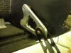
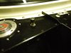
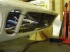
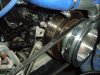
We then started looking at the crank sensor. Pin-out checks were OK, but the ECU didn’t seem to be picking up a speed signal. After checking the sensor function & correct gap, we eventually came to the conclusion, that the sensor was not seeing a clean signal from the trigger wheel. Although the sensor is correctly aligned to the trigger disc, the steel of the TV damper is masking the flux generated between the sensor & tooth (see attached). Not a big problem, I just need to remove the damper and machine a recess next to the trigger wheel to allow the sensor to read a clean signal.

A bit of a set back and I wanted to get this behind me before I went on holiday this week – never mind, something to look forward to on my return.

Regards,
Andy
 

Attachments

  • P9022110.jpg
    P9022110.jpg
    205.7 KB · Views: 458
Andy,
Don't know how far/deep your recess will need to be, but be cognisent of the balance weight on the interior of the dampner. I m assuming you are running an unbalance crank 28/50 oz., or am I wrong on that??

Bill
 
Back
Top