Norfolk Tornado

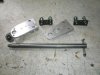
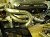
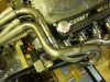
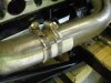
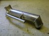
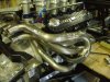
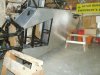
Whilst I’m waiting for some more mandrel bends to arrive to progress the exhaust system, I’ve fabricated my version of the door hinges. The previous builder had made them out of ¾” x1” mild steel and a 5/8” brass hinge pin and would have been over engineered for the door on a Rolls Royce, never mind a lightweight race car.
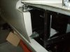
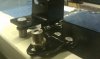
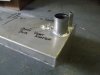
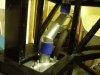
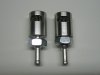
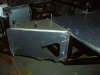
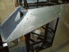
My hinge pin is 5/8” steel tube, which I’ve welded in an M12 nut into the end. This is then screwed into a weld plate which is pop riveted to the lower bracket. The whole point of this is that I can unscrew the hinge pins and remove the door, without changing any of the clearances. Final height adjustment will be with a machined washer, which will eventually be glued to the bottom of the door tube. A captive nut plate also means that I don’t need access to the nuts once the hinges are loosely installed
Regards
Andy
 

Attachments

  • P5311335.jpg
    P5311335.jpg
    33.5 KB · Views: 761
  • P5311339.jpg
    P5311339.jpg
    49.9 KB · Views: 724
Hi Bill,
Thanks for the feedback. The problem for me is that I spend ages deciding on what is the best method for each of the problems as they arise, that’s why this build is taking so long. I’ve already rethought through how to make the height adjustment via the screw thread, but I’ll probably leave that for now.

Regards
Andy
 
Hi Andy

Nice detail mate. Some of the guys in Kent have had issues with the mild steel tube bonded in the door rusting to the mild steel 'pin' this i believe happens on the passenger door as this is the one used less. One chap last year over the winter had the passenger door rust in the closed positon, I was intending to change the tube & pin for stainless steel ? ...an thoughts Andy.

Cannot tell if u have used mild or stainless from brief look

Carry on the good work

KarlB
 
Uncanny how 2 people can be doing thinking th esame things!!!

I am thinking about exhausts and watching yours and thought about the DIY as well. and also door hinges, been away on business and have come to complete hopefully.

With a bit of luck the quick phone picture will show you my take on it. I did not have anything to copy so made it up as i went. Brackets are welded steel, fixxed to chassis with rivnuts at top and captive nuts at bottom with oval holes for alignment. Each bracket has a machined recess to hold the bolts captive and top hat pivots are threaded and so wound up and down to give adjustment. these are currently mild steel but once happy with design (brackets are plan D) then i will make out of SS.

I toyed with idea of one-piece adjustable pin but could not imagine it right in my head....everything seemed to point me in that direction but something nagged me to go the way i did.

Body fitting is killing me and now i have to shave the doors to fit to see if brackets are ok!!!!! i hate bodywork, no fun!!!!
 

Attachments

  • IMAG0050.jpg
    IMAG0050.jpg
    26.9 KB · Views: 718
Hi Karl
The door pins are mild steel, but as long as you bear in mind the steel may rust, it should not be an issue. My plan is to plate the hinge pin & lower nut plate and on final (!!?) assembly liberally grease/copper-slip the pin. I’ll probably add a grease nipple to the tube to ensure it get to where its needed

Hi Ant,
Like yourself, I didn’t have much reference material to take inspiration from. I must admit that your solution probably makes adjustment easier with fore/aft and cross-car adjustment on a separate lock threads. The height adjustment on mine is temporary done with C-washers, so they can be slipped into place during adjustment.

I know what you mean about the body, as I’ve temporary fitted mine to see how bad it is. I’ve currently a ¾” gap between the front & rear clams to the spider section, yet the sill cover is ¾” too long :thumbsdown:

Andy
 

Terry Oxandale

Skinny Man
Whilst I’m waiting for some more mandrel bends to arrive to progress the exhaust system,..

Well Andy, I thought I was going to fall way behind you in completing my headers, but it appears we're both in the same boat. I've been in standby for two weeks waiting for some 4" and 6" radius mandrel bends as well.
 
I’m still progressing very slowly with the exhaust system and now waiting for yet more mandrel bends, hopefully this time they’ll send the correct bend radius! The bit I was dreading, trying to get the pipes to cross-over into the collectors, worked out better than I anticipated. There was some minor tweaking of the pipes with an oxy-acetylene set, but the overall result is acceptable.

So why have I shown a photo of a couple of jubilee clips and two strips of 1mm aluminium, because this is the easiest way to temporary hold the pipes in place before tacking welding. It allows the pipes to be held rigidly in place and fine adjustments, both angular and rotational. Previous attempts with duct tape were OK until it gets too warm in the workshop and the previous clamps I made were too fiddlely.

Regards
Andy
 

Attachments

  • P7121491.jpg
    P7121491.jpg
    51.7 KB · Views: 594
  • P7121492.jpg
    P7121492.jpg
    52.7 KB · Views: 587
  • P7131495.jpg
    P7131495.jpg
    56.6 KB · Views: 619
  • P7191515.jpg
    P7191515.jpg
    38.7 KB · Views: 585
So I could consider the positioning of the AC lines, I needed to get the fuel filler necks fitted first. With a bit of direction from our fuel system specialist at work, the vent pipe into the tank is set to give a 10% (by volume) expansion space. There is also a separate breather pipe which is connected to a roll-over valve which then vents to atmosphere via a small breather cap. I believe that you can buy these from one of the hot-rod shops in the US and Pantera 1889 (Ron) had them on RCR #14 (an inspirational car!), but a bit of time on my lathe I knocked up something very similar.

As I will be mounted the tanks via straps I added an additional boss to earth the tanks to the chassis (another IVA requirement)

Regards
Andy
 

Attachments

  • P6191344.jpg
    P6191344.jpg
    32.6 KB · Views: 527
  • P6191345.jpg
    P6191345.jpg
    40.7 KB · Views: 551
  • P7181508.jpg
    P7181508.jpg
    40.7 KB · Views: 570
  • P7181510.jpg
    P7181510.jpg
    20.3 KB · Views: 537
Finished!!

Well nearly. It now all fits together and I’ve at least 10mm gaps between the pipes, so there’s no localised hot spots. All I’ve got to do now is seam weld & linish 50 odd joints! This has been halted by finally burning out my trusty Black & Decker angle grinder. I must have only had it 25yrs, so I can’t really complain.

In the end I decided to split the manifold flange as it made fitting & removing the exhaust a great deal easier. Overall I’m pretty pleased with the results, with reasonably balanced primary pipes lengths of between 35-38”
On completion of the welding the parts will go away for ceramic coating in satin chrome.

Regards

Andy
 

Attachments

  • P7311511.jpg
    P7311511.jpg
    57 KB · Views: 619
  • P7311515.jpg
    P7311515.jpg
    57.4 KB · Views: 575
  • P7311516.jpg
    P7311516.jpg
    44.4 KB · Views: 580
  • P7311517.jpg
    P7311517.jpg
    59 KB · Views: 601
Absolutely lovely! I like the large radius bends too, which should have lovely gas flows. Looks more like the original bundle of snakes than some of the tight little exhaust layouts we see.

Beautiful work, Andy.Keep it up.
 

Terry Oxandale

Skinny Man
looks great Andy. I bet that feels good to get those out of the way. I'm sure well see som photos of the newly coated headers when they get back?
 
Thanks for the positive feedback guys, but unfortunately I won’t be doing commission work! Looking back on, it wasn’t that difficult, it just takes time. Someone had previously posted that it averaged 8hrs/pipe, which I think is a fair estimation of the amount of time involved.

Whilst waiting for some small tabs to come from the laser cutter which will hold the primary pipes to the collectors. I thought I’d make the silencer heat-shield.

A simple frame was fabricated from 12mm strip steel and this bolts to the silencers. I’ve used is Nimbus GII Heat Shield material from Nimbus Motorsport, which is then riveted to the frame. This material has a double layer aluminium structure, with a dimpled surface to maximise the surface area and is supposed to be the most thermal efficient product currently available. Normally used for turbos etc, it should be good enough for my silencers.

Regards

Andy
 

Attachments

  • P8151497.jpg
    P8151497.jpg
    50.9 KB · Views: 545
  • P8191499.jpg
    P8191499.jpg
    56.1 KB · Views: 545
Andy,
Thats great work. Shame you wont be doing commissions.
When do you expect to be able to fire up the engine now most of it seems done?
 

Terry Oxandale

Skinny Man
Nice Andy!, Simple and light. Can you provide any photos of any supporting structure under the mufflers (if any exists)? I'm still struggling with some kind of support at the rear of the muffler to take some load off the header tubes.
 
Hi Jon,
Although I’d like to see the engine started this year, it still needs to be pulled to finish mounting the front cover and the sump. I’ve also yet to sort the ECU & wiring harness, so at my rate of progress this will be later this year

Hi Terry,
The front of the mufflers are supported on their mounting flanges back to the transmission. This stay bar has a rubber isolator bush built into the lower fixing to provide some damping into the system.
Hope this helps

Regards

Andy
 

Attachments

  • P8211495.jpg
    P8211495.jpg
    54.7 KB · Views: 530
Well it seems a bit odd to be posting pictures of the floor being prepared for riveted on, especially this is normally the first thing that people building Tornado’s do. I’ve only been working on and off the car for nearly 3 years and only now do I feel I’m getting close to start permanently attaching panels to the chassis, so this is a real milestone for me. Even then I’ve been debating whether to have the paint blasted off and get the chassis powder coated :laugh:

The floor pan was originally cut & predrilled over 2 years ago, so it’s good to finally start clearing some space in the workshop. This will eventually be fitted using 4mm sealed rivets. The rear lower panels around engine bay pontoons are to be held on with M5 cap-head screws, to allow access to the fuel system, gear shift etc during build. Drain holes have been added and swaged to aid drainage. The top closure panels had to be remade, as I needed the space to install my exhaust system.

Regards

Andy
 

Attachments

  • P6270752.jpg
    P6270752.jpg
    59.4 KB · Views: 523
  • PA061525.jpg
    PA061525.jpg
    38.7 KB · Views: 522
  • PA061526.jpg
    PA061526.jpg
    49.5 KB · Views: 516
  • PA061527.jpg
    PA061527.jpg
    42 KB · Views: 1,650
Back
Top