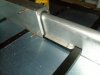
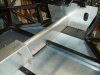
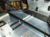
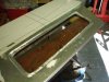
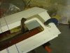
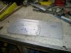
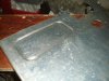
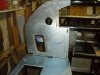
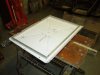
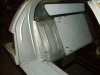
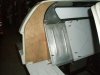
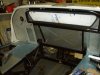
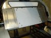
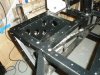
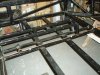
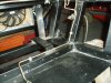
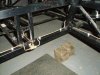
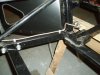
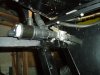
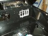
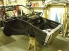
A bit more panelling work:
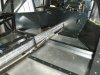
The top of the tunnel has been made removable for access to the handbrake cables and so has the cooling pipe cover in the foot-well area, again retained by M5 cap-head screws. I also plan to run the main electrical harness down here.
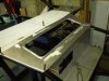
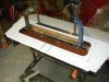
My current thoughts are that only the floor will have carpet on, all remaining panels will be powder-coated satin black, so this is why I taking a bit more time on the fitting & finish of these panels.
Regards
Andy
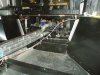
The top of the tunnel has been made removable for access to the handbrake cables and so has the cooling pipe cover in the foot-well area, again retained by M5 cap-head screws. I also plan to run the main electrical harness down here.
My current thoughts are that only the floor will have carpet on, all remaining panels will be powder-coated satin black, so this is why I taking a bit more time on the fitting & finish of these panels.
Regards
Andy